PRODUCTS
We invite you to browse through our product portfolio and compare it against the competitors. We are sure you will agree with us that there is simply no comparison.
- PCI Express Digitizers
- ATS9373 - 12 bit, 4 GS/s
- ATS9360 - 12 bit, 1.8 GS/s
- ATS9364 - 12 bit, 1 GS/s
- ATS9371 - 12 bit, 1 GS/s
- ATS9872 - 8 bit, 1 GS/s
- ATS9362 - 12 bit, 750 MS/s
- ATS9352 - 12 bit, 500 MS/s
- ATS9353 - 12 bit, 500 MS/s
- ATS9628 - 16 bit, 250 MS/s DC
- ATS9462 - 16 bit, 180 MS/s
- ATS9428 - 14 bit, 250 MS/s, DC
- ATS9416 - 14 bit, 100 MS/s, 16ch
- ATS9442 - 14 bit, 125 MS/s, 4 ch
- ATS9440 - 14 bit, 125 MS/s, 4 ch
- ATS9146 - 14 bit, 125 MS/s, 2ch
- ATS9130 - 12 bit, 50 MS/s, 2ch
- ATS9120 - 12 bit, 20 MS/s, 2ch
- Thunderbolt 3 Digitizers
- Software
- Chassis
- Legacy Products
- ATS9870 - 8 bit, 1 GS/s
- ATS9350 - 12 bit, 500 MS/s
- ATS9351 - 12 bit, 500 MS/s
- ATS9625 - 16 bit, 250 MS/s, AC
- ATS9626 - 16 bit, 250 MS/s DC
- ATS660 - 16 bit, 125 MS/s
- ATS460 - 14 bit, 125 MS/s
- ATS330 - 12 bit, 50 MS/s
- ATS310 - 12 bit, 20 MS/s
- ATS860 - 8 bit, 250 MS/s
- ATS850 - 8 bit, 50 MS/s
- AlazarStream 8000
- ATS-VI
- ATS-GMA-BASE
- ATS-GMA-OCT
WELCOME OCT NEWS READERS
AlazarTech provides waveform digitizers (A/D boards) and software solutions that allow OCT users to digitize electronic waveforms generated by their MZI, perform real-time data transfer to GPU for DSP, and easily create live images in their custom imaging software.
ATS9352 is a 12 bit waveform digitizer board that can sample two analog inputs at rates up to 500 MS/s. Get pricing and specifications.
- 500 MS/s sampling rate
- 2 channels sampled at 12-bit resolution
- 128 Megasamples of on-board acquisiton memory per channel
- Variable frequency external clocking
- Additional low-frequency (200 KS/s) input for monitoring feedback signals
- 250 MHz bandwidth
- ±100 mV to ±4 V input range
- Supports OCT Ignore Bad Clock
- 1.6 GB/s PCIe throughput across x4 PCIe Gen2
- Support for Windows & Linux
ATS9352 is ideal for OEMs. Volume pricing available.
ATS9352 customization available for OEMs. Make changes such as:
- On-board galvo-control circuit
- On-FPGA FFT
- Custom FPGA programming
- ...
ATS9146 is a 14 bit waveform digitizer board that can sample two analog inputs at rates up to 125 MS/s. Get pricing and specifications.
- 125 MS/s sampling rate
- 2 channels sampled at 14-bit resolution
- 128 Megasamples of on-board acquisiton memory per channel
- Variable frequency external clocking
- Up to 65 MHz bandwidth
- ±20 mV to ±10 V input range
- 200 MB/s PCIe throughput across x1 PCIe Gen1
- Support for Windows & Linux
ATS9130 is a 12 bit waveform digitizer board that can sample two analog inputs at rates up to 50 MS/s. Get pricing and specifications.
- 50 MS/s sampling rate
- 2 channels sampled at 12-bit resolution
- 8 Megasamples of on-board acquisiton memory per channel
- Variable frequency external clocking
- Continuous streaming mode
- Up to 25 MHz bandwidth
- ±40 mV to ±20 V input range
- 200 MB/s PCIe throughput across x1 PCIe Gen1
- Support for Windows & Linux
ATS9120 is a 12 bit waveform digitizer board that can sample two analog inputs at rates up to 20 MS/s. Get pricing and specifications.
- 20 MS/s sampling rate
- 2 channels sampled at 12-bit resolution
- 8 Megasamples of on-board acquisiton memory per channel
- Variable frequency external clocking
- Continuous streaming mode
- Up to 10 MHz bandwidth
- ±40 mV to ±20 V input range
- 200 MB/s PCIe throughput across x1 PCIe Gen1
- Support for Windows & Linux
If your OCT system must operate on a 24/7 basis, you need to use AlazarTech products.
AlazarTech provides a complete solution for SS-OCT applications, including:
- Low Noise High Resolution data acquisition at fast sample rates With up to 4 GS/s sampling offered by ATS9373, you can future-proof your OCT system for tomorrow's sources
- Fast 6.8 GB/s data transfer rate for raw (time domain) data or FFT data There are OTHER companies claiming to offer OCT solutions, but their data transfer rate to computer memory is only a few hundred Megabytes per second, putting a ceiling on how many frames per second they can capture
-
Support for variable frequency external clock to allow the use of the swept source's k-clock to solve the re-linearization problem This feature is unique to AlazarTech due to our unique A/D technology. Commercially available A/D technology requires fixed frequency sampling and, therefore, cannot use k-clock signals from swept sources. A DSP-based resampling scheme must be used to linearize the data in k-space. Our k-clock based solution directly generates data linear in k-space
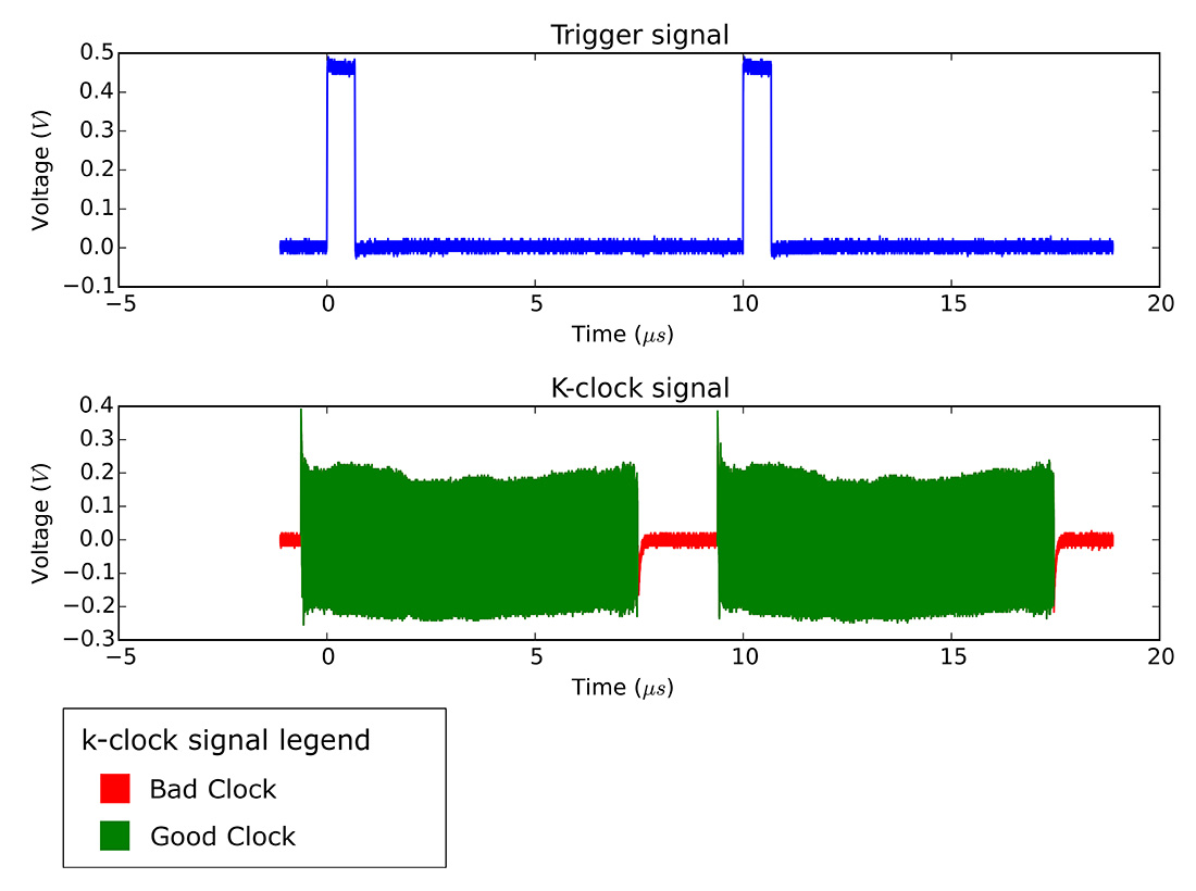
- Unique OCT Ignore Bad Clock feature that allows use of out-of-specification k-clocks k-clock from many swept sources provide either no signal in between scans or a "dummy clock" of very slow frequency. In some cases, the "dummy clock" can also contain glitches. AlazarTech's OCT Ignore Bad Clock technology allows the user to tell the A/D circuitry to ignore the k-clock signal during a certain time duration after each trigger
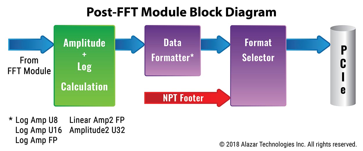
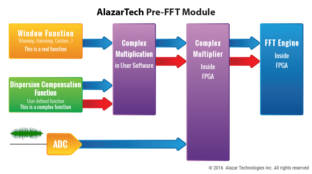
- Complete on-FPGA FFT solution that includes: • User programmable dispersion compensation function
• User programmable windowing
• Log calculation
• FFT magnitude output in floating point or integer format
- Special "Raw + FFT" mode that allows users to acquire both time domain and FFT data This can be very useful during the validation process
- Embedded data footers that include timestamp, frame count and many other useful information for each record