PRODUITS
Nous vous invitons à consulter notre portefeuille de produits et à le comparer à la concurrence.
- Cartes d’acquisition PCI Express
- ATS9380 - 12 bit, 10 Géch/s
- ATS9373 - 12 bit, 4 Géch/s
- ATS9360 - 12 bit, 1.8 Géch/s
- ATS9364 - 12 bit, 1 Géch/s
- ATS9371 - 12 bit, 1 Géch/s
- ATS9872 - 8 bit, 1 GS/s
- ATS9362 - 12 bit, 750 Méch/s
- ATS9352 - 12 bit, 500 Méch/s
- ATS9353 - 12 bit, 500 Méch/s
- ATS9628 - 16 bit, 250 Méch/s, DC
- ATS9462 - 16 bit, 180 Méch/s
- ATS9428 - 14 bit, 250 Méch/s, DC
- ATS9416 - 14 bit, 100 Méch/s, 16can
- ATS9442 - 14 bit, 125 MS/s, 4 ch
- ATS9440 - 14 bit, 125 Méch/s, 4can
- ATS9146 - 14 bit, 125 Méch/s, 2can
- ATS9130 - 12 bit, 50 Méch/s, 2can
- ATS9120 - 12 bit, 20 Méch/s, 2can
- Cartes d’acquisition Thunderbolt 3
- Logiciels
- Châssis
- Produits patrimoniaux
- ATS9870 - 8 bit, 1 Géch/s
- ATS9350 - 12 bit, 500 Méch/s
- ATS9351 - 12 bit, 500 Méch/s
- ATS9625 - 16 bit, 250 Méch/s, CA
- ATS9626 - 16 bit, 250 Méch/s, DC
- ATS660 - 16 bit, 125 Méch/s
- ATS460 - 14 bit, 125 Méch/s
- ATS330 - 12 bit, 50 Méch/s
- ATS310 - 12 bit, 20 Méch/s
- ATS860 - 8 bit, 250 Méch/s
- ATS850 - 8 bit, 50 Méch/s
- AlazarStream 8000
- ATS-VI
- ATS-GMA-BASE
- ATS-GMA-OCT
QUESTIONS FRÉQUEMMENT POSÉES
Impossible de trouver une réponse?
Contacter le support technique
[1093] J'essaie d'installer ma licence ATS-SDK en utilisant Alazar Package Manager et la clé de licence ne fonctionne plus. J'ai pu l'installer dans le passé. Ma clé de licence n'est-elle plus valide ?
Lien vers cette réponse:  Copié
Copié
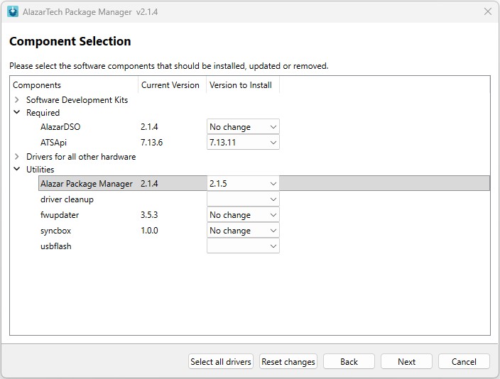
Assurez-vous d'utiliser votre clé de licence avec la dernière version du Gestionnaire de Paquets Alazar.
Pour des raisons de sécurité, AlazarTech modifie régulièrement ses clés d'accès au dépôt de stockage. L'utilisation de la dernière version du Gestionnaire de Paquets assure la compatibilité avec les clés d'accès actuelles.
Vous pouvez mettre à jour le Gestionnaire de Paquets directement à partir de la section « Utilities » du Gestionnaire de Paquets :
Les clés de licence ATS-SDK et ATS-GPU vous permettront toujours d’installer la dernière version disponible au moment de l’expiration de votre abonnement.
Si vous installez ATS-SDK ou ATS-GPU sous Linux, veuillez utiliser l'un des installateurs ATS-License suivants :
[1092] Pourquoi l'ATS9442 n'offre-t-il que 128 Mo de mémoire, alors que l'ATS9440 pouvait offrir jusqu'à 2 Go de mémoire ?
Lien vers cette réponse: Copié
ATS9440, introduit à l'origine dans les années 2010, utilisait un moteur DMA qui nécessitait l'intervention du pilote logiciel afin de réarmer le DMA. Cela a créé une latence non déterministe entre la fin d'un DMA et le début du suivant. La latence peut être aussi courte que 100 μs et aussi longue que 10 millisecondes.
Afin de garantir un transfert de données sans interruption, la mémoire embarquée devait être suffisamment longue pour stocker les données en mémoire tampon pour la pire latence. Nous avons donc offert la possibilité d'aller aussi loin que la technologie de la mémoire le permettait à ce moment-là.
Sur ATS9442, le moteur DMA est réarmé dans le matériel, ce qui se fait en quelques centaines de nanosecondes. Par conséquent, il n'est pas nécessaire d'ajouter de la mémoire embarquée au-delà de ce qui est requis pour le fonctionnement normal du DMA. Une mémoire de 128 M est plus que suffisante à cette fin.
Un autre problème sur ATS9440 était qu'en mode 2 ou 4 canaux, la mémoire devait être lue plusieurs fois pour fournir des données non entrelacées. Les utilisateurs devaient régler le mode de données entrelacées pour obtenir toute la bande passante de transfert de données.
Le sous-système de mémoire ATS9442 a été conçu pour permettre le transfert de données non entrelacées via DMA sans aucune pénalité.
[1091] My ATS9373 is not recognized by my new PCIe Gen5 Dell Precision Tower 5860 computer. Can you help me? (also applies to ATS9371, ATS9364, ATS9362, ATS9437, and ATS9637)
Lien vers cette réponse: Copié
PCIe Gen5 includes a new feature called Data Link Feature Exchange (DLF or DLFE), which is not supported by PCIe Gen 3 (this feature did not exist when PCIe Gen 3 was introduced). Most computers have this DLF feature set to “Enabled” or “Auto”, thus becoming incompatible with PCIe Gen 3 adapters, such as ATS9373.
July 2025 UPDATE: The July 9, 2025 release of DELL Precision 5860 BIOS version 3.0.2 includes the PCIe Data Link Feature Exchange Option. Customers who wish to use this computer with AlazarTech Gen 3 digitizers (ATS9373, ATS9371, ATS9364, ATS9362, ATS9437, and ATS9637) must update their BIOS to version 3.0.2 (or later) and modify the DLFE settings: https://www.dell.com/support/home/en-ca/drivers/driversdetails?driverid=h5w95&oscode=wt64a&productcode=precision-5860-workstation
FAQ 1091 History:
When initially validating the DELL Precision 5860 for use with the ATS9373 in November 2024, we noted that Dell did not have a Data Link Feature Exchange setting in their BIOS version 2.4.1. We contacted Dell technical support through their website, and after exchanging several emails, their support team informed us that the Dell 5860 does not support PCIe Gen 3 adapters. For this reason, we issued this FAQ stating that we did not recommend the Dell 5860 for AlazarTech PCIe Gen 3 digitizers but that it was suitable for our PCIe Gen 1, Gen 2 and Gen 4 digitizers.
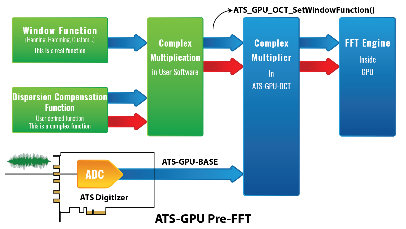
[1090] Using ATS-GPU-OCT, I am able to download a custom window function to my GPU using ATS_GPU_OCT_SetWindowFunction(). How do I download a custom dispersion compensation function to my GPU?
Lien vers cette réponse: Copié
Users can implement dispersion compensation by doing a pointwise multiplication of the real window function with the complex dispersion compensation function.
The resulting complex function is then set by calling ATS_GPU_OCT_SetWindowFunction().
[1088] Comment puis-je faire une demande de prix sur www.alazartech.com ?
Lien vers cette réponse: Copié
- Inscrivez-vous en tant qu'utilisateur sur le site Web d'Alazartech; Si vous êtes déjà un utilisateur enregistré, veuillez vous connecter et passer à l'étape suivante.
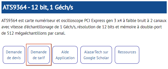
- Ensuite, accédez à la page de produit duquel vous souhaitez des prix. Dans cet exemple, nous utilisons la page du produit ATS9364.
- Cliquez sur le bouton Demande de tarif .
- La demande de prix sélectionnée sera par défaut le produit de la page à partir de laquelle vous avez cliqué sur Demande de tarif. Dans cet exemple, il s'agit du produit «ATS9364 - 12 bit, 1 Géch/s».
Ajoutez des détails sur votre application dans la zone de texte «Détails supplémentaires concernant votre application».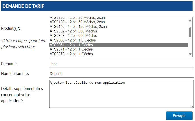
Remarque : Vous pouvez utiliser la touche [ctrl] et cliquer sur d’autres produits pour effectuer plusieurs sélections, comme indiqué ci-dessous : 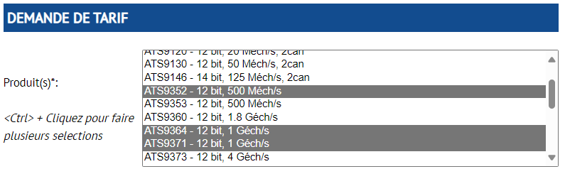
- Cliquez sur le bouton « Envoyer » en bas à droite et la ou les listes de prix demandée(s) seront envoyées à l’adresse courriel que vous avez utilisée lors de votre inscription sur le site Web.
[1087] My ATS9373 is not being recognized by my new computer with Supermicro PCIe Gen5 motherboard. Can you help me? (also applies to ATS9371, ATS9364, ATS9362, ATS9437, and ATS9637)
Lien vers cette réponse: Copié
PCIe Gen4 and Gen5 include a new feature called Data Link Feature Exchange (DLF or DLFE), which is not supported by PCIe Gen3. For a Gen3 adapter to work in a Gen5 motherboard, DLFE must be set to “Disabled” in the BIOS.
Some customers have reported that Supermicro does include a Data Link Feature Exchange setting in their BIOS.
Supermicro X13SRA-TF: A customer successfully used ATS9373 in this motherboard after choosing “Disabled” as the value for Data Link Feature Exchange setting in the BIOS.
Supermicro AS-2125HS-TNR: A customer reported that there was no Data Link Feature Exchange setting in BIOS v1.4 for this motherboard. Supermicro provided them with a new BIOS (v1.6), but they could not update the BIOS with the ATS9373 inserted in a PCIe slot. They had to remove the ATS9373 to do a BIOS update. Once they had the new BIOS, they found that Data Link Feature Exchange setting is hidden by default. To see this setting, another BIOS setting had to be “Enabled”:
Advanced è NB Configuration è Data Link Feature Cap [Enabled]
Once this setting was “Enabled”, they could set Data Link Feature Exchange to “Disabled”:
Advanced è NB Configuration è Data Link Feature Exchange [Disabled]
If you cannot find the Data Link Feature Exchange setting in your BIOS, contact ASRock. It is their responsibility to provide you with this setting in their BIOS.
https://www.supermicro.com/en/support
[1086] My ATS9373 is not being recognized by my new PCIe Gen5 HP Z4 G5 computer. Can you help me? (also applies to ATS9371, ATS9364, ATS9362, ATS9437, and ATS9637)
Lien vers cette réponse: Copié
PCIe Gen4 and Gen5 include a new feature called Data Link Feature Exchange (DLF or DLFE), which is not supported by PCIe Gen3. For a Gen3 adapter to work in a Gen5 motherboard, DLF must be set to “Disabled” in the BIOS.
It is recommended that you remove the ATS9373 from the motherboard slot when you have to update the BIOS.
Customers using Z4 G5 and Z6 G5 computers have reported that HP does include a Data Link Feature setting in their BIOS.
BIOS Setup è Advanced è Slot Settings è (select PCIe x16 slot used for AlazarTech digitizer installation)
On the page for the selected PCIe slot, make the following changes:
- Limit PCIe Speed [Gen 3 (8Gbps)]
- Bifurcation [x8x8]
- PCIe Data Link Feature [Disable]
If you cannot find the Data Link Feature Exchange setting in your BIOS, contact HP. It is their responsibility to provide you with this setting in their BIOS.
[1085] My ATS9373 is not being recognized by my new computer with ASUS Pro WS W790E-SAGE-SE PCIe Gen5 motherboard. Can you help me? (also applies to ATS9371, ATS9364, ATS9362, ATS9437, and ATS9637)
Lien vers cette réponse: Copié
PCIe Gen4 and Gen5 include a new feature called Data Link Feature Exchange (DLF or DLFE), which is not supported by PCIe Gen3. For a Gen3 adapter to work in a Gen5 motherboard, DLFE must be set to “Disabled” in the BIOS.
It is recommended that you remove the ATS9373 from the motherboard slot when you have to update the BIOS.
A customer with an ASUS Pro WS W790E-SAGE-SE reported that their ATS9373 was not being recognized in any of the slots. Furthermore, their original BIOS v4401 did not have a menu item for this feature.
We contacted ASUS technical support through their website and their engineering group very quickly produced a BIOS version 9901 that allowed Data Link Feature Exchange to be turned off on a slot-by-slot basis:
Socket Config è IIO Configuration è Socket0 Configuration è Data Link Feature Exchange
We are putting this custom BIOS version at your disposal here1.
The customer planned to plug the ATS9373 board in Slot 4 of the motherboard, so they turned off the Data Link Feature Exchange setting for Slot 4 only.
As a result, the customer’s computer was able to enumerate ATS9373 as a PCIe Gen3 x8 device.
If you cannot find the Data Link Feature Exchange setting in your BIOS, contact ASUS. It is their responsibility to provide you with this setting in their BIOS.
https://www.asus.com/us/support/
1In no event shall Alazar Technologies Inc. be liable to you or any third parties for any special, punitive, incidental, indirect, or consequential damages of any kind, or any damages whatsoever, including, without limitation, those resulting from loss of use, lost data, or profits, or any liability, arising out of or in connection with the use of this software.
[1084] My ATS9371 is not being recognized by my new computer with ASRock PCIe Gen5 motherboard. Can you help me? (also applies to ATS9373, ATS9364, ATS9362, ATS9437, and ATS9637)
Lien vers cette réponse: Copié
PCIe Gen4 and Gen5 include a new feature called Data Link Feature Exchange (DLF or DLFE), which is not supported by PCIe Gen3. For a Gen3 adapter to work in a Gen5 motherboard, DLFE must be set to “Disabled” in the BIOS.
It is recommended that you remove the ATS9371 from the motherboard slot when you have to update the BIOS.
A customer with an ASRock B650M PG Riptide reported that their ATS9371 was not being recognized in any of the slots. Furthermore, their original BIOS as well as the latest available BIOS version did not have a menu item for this feature.
They contacted ASRock technical support through their website and the ASRock engineering group produced a custom BIOS version that disabled Data Link Feature Exchange.
The customer was not able to find the DLFE menu item in the new BIOS, but it did solve the issue and the customer’s computer was able to enumerate ATS9371 as a PCIe Gen3 x8 device. We are putting this custom BIOS version at your disposal here1.
If you cannot find the Data Link Feature Exchange setting in your BIOS, contact ASRock. It is their responsibility to provide you with this setting in their BIOS.
https://tw.asrock.com/events/tsd.us.asp
1In no event shall Alazar Technologies Inc. be liable to you or any third parties for any special, punitive, incidental, indirect, or consequential damages of any kind, or any damages whatsoever, including, without limitation, those resulting from loss of use, lost data, or profits, or any liability, arising out of or in connection with the use of this software.
[1083] My ATS9373 is not being recognized by my new computer with a PCIe Gen5 motherboard. Can you help me? (also applies to ATS9371, ATS9364, ATS9362, ATS9437, and ATS9637)
Lien vers cette réponse: Copié
PCIe Gen4 and Gen5 include a new feature called Data Link Feature Exchange (DLF or DLFE), which is not supported by PCIe Gen3 (this feature did not exist when PCIe Gen3 was introduced). Most motherboards have this DLF feature set to “Enabled” or “Auto”, thus becoming incompatible with PCIe Gen 3 adapters, such as ATS9373.
- For a Gen3 adapter to work in a Gen5 motherboard, Data Link Feature Exchange must be set to “Disabled” in the BIOS.
Unfortunately, some manufacturers do not provide this setting in the BIOS. We have encountered this issue with certain Asrock (more on that here) and ASUS motherboards (more on that here).
Your computer should have the Data Link Feature Exchange setting somewhere in the BIOS. Please set it to “Disabled”. It is recommended that you remove the ATS9373 from the motherboard slot when you have to update the BIOS.
To help customers who are experiencing these issues, we have created separate FAQs for cases where we can provide more detailed information. If you do not see your motherboard manufacturer in the list below and you are unable to find the Data Link Feature Exchange in your BIOS settings, please contact your motherboard manufacturer; a list of support links is provided at the end of this FAQ for your convenience.
FAQ 1084: Asrock PCIe Gen5 not recognizing PCIe Gen 3
FAQ 1085: ASUS PCIe Gen5 not recognizing PCIe Gen 3
FAQ 1086: HP Z4 G5 (or Z6 G5) PCIe Gen5 not recognizing PCIe Gen 3
FAQ 1087: Supermicro PCIe Gen5 not recognizing PCIe Gen 3
FAQ 1091: Dell Precision Tower 5860 not recognizing PCIe Gen 3
If you cannot find the Data Link Feature Exchange setting in your BIOS, contact your motherboard manufacturer. It is their responsibility to provide you with this setting in their BIOS.
Motherboard manufacturer support resources (as of FAQ1083 publication date of July 23, 2024):
Asrock: https://tw.asrock.com/events/tsd.us.asp
ASUS: https://www.asus.com/us/support/
Dell: https://www.dell.com/support/incidents-online/en-us/contactus/dynamic
GIGABYTE: https://www.gigabyte.com/Support
HP: https://support.hp.com/us-en
MSI: https://www.msi.com/support/mb
Supermicro: https://www.supermicro.com/en/support
[1082] Comment puis-je accéder aux modèles STEP des numériseurs AlazarTech ?
Lien vers cette réponse: Copié
Les modèles STEP (STP) 3D sont des téléchargements restreints.
Les téléchargements restreints ne sont disponibles que pour les clients qui ont enregistré leur numériseur AlazarTech. De plus, l'accès n'est disponible que pour le produit enregistré (par exemple, vous ne pouvez accéder aux téléchargements restreints ATS9364 que si vous disposez d'un ATS9364 enregistré).
D'autres exemples de téléchargements restreints sont les anciennes versions de pilotes et les rapports de prévision de fiabilité.
Vous pouvez enregistrer votre produit ici.
Veuillez noter: vous devez être connecté à votre compte AlazarTech.com pour enregistrer un produit. Vous n’avez pas de compte? Créez-en un ici.
[1081] I moved my ATS9373 into a Gen 5 x8 slot in a new computer and the computer is not recognizing the card. Is there a compatibility issue with AlazarTech digitizers and PCIe Gen 5?
Lien vers cette réponse: Copié
We have seen an issue in PCIe Gen4 & Gen5 BIOS that causes problems with Gen3 devices:
A BIOS feature called "Data link feature exchange" must be disabled.
How to check if this feature exists in your motherboard’s BIOS:
1. Turn off the computer
2. Remove AlazarTech PCIe Gen 3 Digitizer from the PCIe slot in the computer. It is very important that the AlazarTech PCIe Gen 3 Digitizer is not plugged into the computer when you make the BIOS change. If the BIOS is updated while the AlazarTech Digitizer is installed, it will never recognize the AlazarTech Digitizer, no matter how the BIOS settings are changed. A complete re-installation of the BIOS will be required for the BIOS to recognize the AlazarTech Digitizer.
3. Turn on the computer and go into the BIOS
- Depending on the BIOS, you may have to turn some options on to see the “Data link feature exchange” setting
- On the Supermicro AS-2125HS-TNR
BIOS v1.6:
Advanced -> NB Configuration -> Data Link Feature Cap [Enabled]
4.
Disable "Data link feature
exchange".
Reminder: it is very important that AlazarTech Digitizer is not plugged into
the computer when you make BIOS change.
- On the Supermicro AS-2125HS-TNR
BIOS v1.6:
Advanced -> NB Configuration -> Data Link Feature Exchange [Disabled]
5. Save BIOS
6. Power down the computer
7. Insert AlazarTech Digitizer into a PCIe slot
8. Power on the computer
9. The AlazarTech PCIe Gen 3 Digitizer should now be recognized
[1080] Où puis-je trouver le fichier log AlazarDSO ?
Lien vers cette réponse: Copié
Vous pouvez le trouver dans le dossier …/Documents/AlazarTech. Le fichier s'appelle AlazarDSO.log.
La FAQ suivante pourrait vous intéresser :
[1079] Où puis-je trouver le fichier log ATSApi ?
Lien vers cette réponse: Copié
Vous pouvez le trouver dans votre dossier TEMP (vous pouvez rechercher %TEMP% pour le trouver). Le fichier s’appelle ATSApi.log.
Les FAQ suivantes pourraient vous intéresser :
Comment puis-je utiliser l’utilitaire ApiFlags pour enregistrer les appels d’API ?
[1078] Je veux rétablir la garantie de mon numériseur et on m’a dit que je devais prouver que mon numériseur fonctionne. Comment dois-je procéder ?
Lien vers cette réponse: Copié
In order to reinstate a lapsed digitizer warranty, customers must first confirm that the digitizer is in working order by running the following tests:
- Run AlazarDSO for MS-Windows (or AlazarFrontPanel for Linux)
-
Press [ F4 ]
o Is the on-board memory recognized? Or is the board “FIFO”
o Is the PCIe link width as expected?
- Connect 1 MHz , +/- 300mV sine wave signal to CH A
- Set CH A input range to be +/- 400 mV (or the closest)
- Acquire and make sure the signal frequency is 1 MHz and amplitude is +/- 300mV +/- 2%
- Does the board trigger on positive slope of sine wave when Trigger slope is set to Rising?
- Does the board trigger on negative slope of sine wave when Trigger slope is set to Falling?
Please send the test results to sales@alazartech.com along with your board serial number and request for quote for warranty reinstatement.
More details on AlazarTech Warranty Reinstatement Program
[1077] I have a workstation with a Pro-Art X670E-Creator motherboard with an AMD Ryzen 7000 Series Processor and my ATS9373 is not being recognized. Is this a known issue?
Lien vers cette réponse: Copié
We have had reports of certain CPUs with Gen5 support having issues with recognizing 8-lane Gen3* boards.
This motherboard's specifications state that it has two PCIe 5.0 x16 slots that support x16 or x8/x8 modes. By default, they are set to x16.
To fix the issue of systems not recognizing 8-lane PCIe Gen 3 boards, you must change the PCIe bifurcation in the BIOS to specify 8 lanes for the GPU and 8 lanes for the digitizer (x8/x8).
This motherboard manufacturer's documentation states that there is a BIOS mode where users can specify bifurcation. However, at time of publication of this FAQ, this mode does not appear in the actual BIOS. The BIOS only allows the following two PCIe bifurcations:
- GPU slot has 16 lanes and the PCIe expansion slot has no lanes
- Auto
If the first option is chosen, the computer does not boot up.
If "Auto" is chosen, the computer boots up, but the PCIe Gen3 x 8 board is not recognized.
This points to a bug in the BIOS that does not negotiate PCIe Gen3 x8 link properly. This can only be fixed by the motherboard manufacturer.
* PCIe Gen1, Gen2, and PCIe Gen4 boards are not affected by this issue and are properly recognized
[1076] I have a new HP Z4G5 workstation and my ATS9373 is not being recognized, but it works fine in my older HP Z4. Is this a known issue?
Lien vers cette réponse: Copié
We have had reports of certain CPUs with Gen5 support having issues recognizing 8-lane Gen3* boards.
By default, the 20 lanes are assigned as 16 for PCIe and 4 for NVME.
To fix the issue of systems not recognizing 8-lane PCIe Gen 3 boards, you must change the PCIe bifurcation in the BIOS to specify 8 lanes for the GPU and 8 lanes for the digitizer.
Note that some motherboards, such as Pro-Art X670E-Creator, will not allow the bifurcation. This points to a bug in the BIOS that does not negotiate PCIe Gen3 x8 link properly. This can only be fixed by the motherboard manufacturer.
* PCIe Gen1, Gen2 and PCIe Gen4 boards are not affected by this issue and are properly recognized
[1075] Comment utiliser Package Manager pour installer ATS-SDK et ATS-GPU
Lien vers cette réponse: Copié
To install ATS-SDK and/or ATS-GPU:
1. Run the latest version of Alazar Package Manager. If it is not already installed, download the latest version of Alazar Package Manager from www.alazartech.com/apmf
2. On the Introduction page:
2.1 Enter your license key (FAQ on how to get a license key);
2.2 Select the SDK type from the pull-down menu;
2.3 Click Add.
2.4 Repeat steps 2.1 to 2.3 if you have more than one type of SDK to install, then click Next.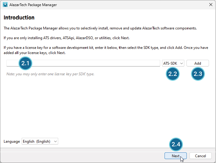
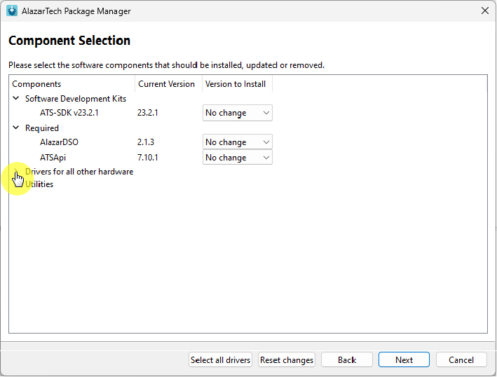
3. Follow the on-screen prompts to install the software. At the Component Selection screen, you may install any AlazarTech digitizer drivers and Utilities you need. If you already have AlazarTech drivers or Utilities installed, Alazar Package Manager will automatically install the latest version during this installation. Expand the Drivers for all other hardware and Utilities sections to see available items and to change the versions to install.
4. The Installation Summary screen will display a list of all items to be installed and/or upgraded. Click Proceed to complete the installation.
5. The SDK guide is installed with the software. Navigate to the installation location (default is C:\AlazarTech) to view the manual.
[1074] J’essaie d’installer la dernière version d’ATS-SDK et d’ATS-GPU-BASE. Les versions précédentes étaient des fichiers ZIP protégés par mot de passe, mais le lien de la dernière version installe Alazar Package Manager et nécessite une clé de licence. Comment puis-je obtenir une clé de licence ?
Lien vers cette réponse: Copié
Le gestionnaire de paquets AlazarTech est une application conçue pour aider à installer, supprimer, mettre à jour et réparer les logiciels AlazarTech sur les ordinateurs Windows.
Avec la version 2.0.0 du gestionnaire de paquets AlazarTech, vous pouvez installer vos SDK AlazarTech, installer/mettre à jour vos pilotes et utilitaires AlazarTech, ainsi que AlazarDSO. Le gestionnaire de paquets AlazarTech 2.0.0 est capable d’installer ATS-SDK v23.3.0 et versions ultérieures, et ATS-GPU v23.1.1 et versions ultérieures.
Comment obtenir votre clé de licence SDK (ATS-SDK & ATS-GPU)
Les clients qui ont acheté leur SDK après le 1er novembre 2023 devraient voir leur clé de licence sur leur facture et dans leur courriel de livraison électronique pour le SDK.
Les clients qui ont acheté leur SDK avant le 1er novembre 2023 et dont les SDK sont toujours sous maintenance au 1er novembre 2023 doivent enregistrer leur SDK ici www.alazartech.com/fr/my-account/my-products/register/ pour obtenir leur clé de licence. Une fois que l'enregistrement du produit est confirmé, la clé de licence apparaîtra sous Compte --> Mes produits www.alazartech.com/fr/my-account/my-products/. Si vous avez déjà enregistré votre SDK, vous devriez déjà pouvoir voir votre clé de licence.
Les clients dont la maintenance du SDK a expiré avant le 1er novembre 2023 doivent continuer à utiliser les fichiers ZIP protégés par mot de passe des anciennes versions auxquelles ils ont droit.
Comment utiliser Package Manager pour installer ATS-SDK et ATS-GPU.
[1073] Certains téléchargements sont réservés aux utilisateurs disposant d’un produit enregistré. Comment puis-je enregistrer mon produit ?
Lien vers cette réponse: Copié
Restricted downloads are only available to customers who have registered their AlazarTech digitizer. Furthermore, access is only available for the registered product (e.g. you can only access ATS9364 restricted downloads if you have a registered ATS9364).
Restricted downloads include 3D STEP (STP) models, older versions of drivers, and Reliability Prediction Reports.
Please follow these steps to register your product:
Step 1: If you have not already done so, register yourself on the alazartech.com website: www.alazartech.com/en/register/
You will receive an activation email; you must activate your account to finalize registration.
Step 2: To register your product, go to www.alazartech.com/en/my-account/my-products/register/
You will be asked to sign-in to your alazartech.com account if you are not already signed-in.
Step 3: Select your Product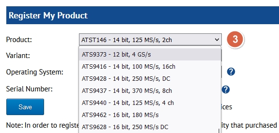
Step 4: If applicable, select your Variant (it will be marked [N/A] if not applicable)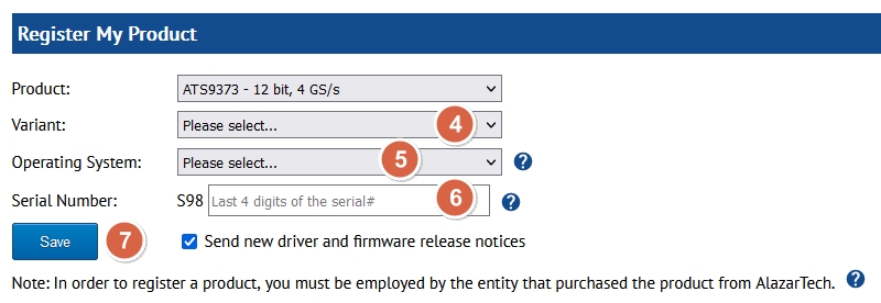
Step 5: Select your Operating System.
Step 6: Type in the last 4 digits of your board Serial Number.
Step 7: Click Save. This will send your board information to AlazarTech. We will review the submitted information and approve the registration if the provided information matches our records.
[1072] Je ne vois pas ATST146 dans le gestionnaire de paquets AlazarTech. Quel pilote dois-je installer ?
Lien vers cette réponse: Copié
Vous devez installer le pilote ATS9146
[1071] Lorsque j’installe un numériseur Thunderbolt 3, je reçois un message d’avertissement à l’écran indiquant que les capacités peuvent être limitées. Comment puis-je obtenir toutes les capacités de mon numériseur Thunderbolt 3 ?
Lien vers cette réponse: Copié
La sécurité Thunderbolt est gérée par votre carte mère. Vous devez autoriser explicitement l’installation d’un périphérique Thunderbolt. Habituellement, vous n’avez à le faire que la première fois que vous utilisez l’appareil.
Pour plus d’informations à ce sujet, rendez-vous sur : https://www.thunderbolttechnology.net/security/Thunderbolt%203%20and%20Security.pdf
[1070] Pourquoi y a-t-il un si grand écart dans les numéros de version ATS-SDK ? Le dernier était v7.7.0 et maintenant c'est v23.1.0
Lien vers cette réponse: Copié
Suite à des commentaires de la part de nos clients, nous avons décidé de modifier le processus de publication d’ATS-SDK. À partir de 2023, des nouvelles versions ou mises à jour d’ATS-SDK seront publiées sur une base trimestrielle.
Le numéro de version a été mis à jour pour refléter ce nouveau calendrier trimestriel pour les versions ATS-SDK et signifie : Année.Trimestre.Correctif. La première version de ce type a été réalisée vers la fin du mois de mars 2023 et s’appelle v23.1.0
La prochaine version prévue en fin juin 2023 s’appellera 23.2.0.
Si jamais nous devons faire une version avant la version prévue du trimestre suivant, son numéro de version aura le dernier champ incrémenté, par exemple 23.1.1.
[1069] I noticed some contradictory documentation for the API function AlazarAllocBufferU16 (). One place stated that the second parameter to this call, byteCount, should be set in number of samples, whereas another place it called for number of bytes. Can you clarify?
Lien vers cette réponse: Copié
The second parameter of AlazarAllocBufferU16 (), byteCount, should be specified in bytes.
Documentation was recently updated to correct the contradiction between various documents.
Please check ATS-SDK guide on our website for the correction:
[1068] Some of my signal happens before the trigger comes in. Can I capture some pre-trigger data even if I am in NPT mode?
Lien vers cette réponse: Copié
Yes, you can capture limited amount of pre-trigger data even if you are acquiring in NPT (No Pre Trigger) mode. Many customers run into a situation very similar to yours and to help them, we have added the capability of having a limited number of pre-trigger points in NPT mode.
To appropriately configure an NPT acquisition with pre-trigger samples, you need to set the two following APIs:
1. Add a call to AlazarSetRecordSize () before you call AlazarBeforeAsyncRead (). In this call, you will specify how many pre-trigger and post-trigger samples you want. Note that the sum of (number of pre-trigger samples) and (number of post trigger samples) must be equal to Record Length
retCode = AlazarSetRecordSize(boardHandle, preTriggerSamples, postTriggerSamples);
where samplesPerRecord = preTriggerSamples + postTriggerSamples;
2. In the call to AlazarBeforeAsyncRead (), make sure you pass a negative value for the transferOffset field. This should be equal to (-number of pre-trigger samples):
retCode = AlazarBeforeAsyncRead(boardHandle, channelMask, -(long)preTriggerSamples,
samplesPerRecord, recordsPerBuffer, recordsPerAcquisition,
admaFlags);
Note that it is essential that samplesPerRecord = preTriggerSamples + postTriggerSamples;
[1067] Je souhaite acheter du logiciel AlazarTech pour l'utiliser avec une carte numériseur que j'ai déjà. La fiche technique du logiciel indique que je dois effectuer quelques tests au préalable. Que sont-ils?
Lien vers cette réponse: Copié
In order to avoid possible disappointment in product functionality, customers purchasing ATS-SDK or an ATS-GPU library for use with an out-of-warranty waveform digitizer must first confirm that the digitizer is in working order by running the following tests:
- Run AlazarDSO for MS-Windows (or AlazarFrontPanel for Linux)
-
Press [ F4 ]
o Is the on-board memory recognized? Or is the board “FIFO”
o Is the PCIe link width as expected?
- Connect 1 MHz , +/- 300mV sine wave signal to CH A
- Set CH A input range to be +/- 400 mV (or the closest)
- Acquire and make sure the signal frequency is 1 MHz and amplitude is +/- 300mV +/- 2%
- Does the board trigger on positive slope of sine wave when Trigger slope is set to Rising?
- Does the board trigger on negative slope of sine wave when Trigger slope is set to Falling?
Please send the test results to sales@alazartech.com along with your request for quote or your software pricing inquiry.
[1066] Votre devis inclut-il les taxes d’importation (TVA) vers l’Allemagne ou un autre pays de l’UE ?
Lien vers cette réponse: Copié
Nos devis aux clients de l’UE sont destinés à la vente de produits sur une base intracommunautaire. Cela signifie qu’AlazarTech importe les marchandises dans l’UE dans notre centre logistique d’Amsterdam à nos propres frais et expédie ensuite les marchandises d’Amsterdam à votre établissement.
La TVA pour l’importation est comptabilisée auprès des autorités fiscales néerlandaises sous le numéro de TVA d’AlazarTech. En tant que tel, vous pouvez traiter cet achat comme tout autre achat transfrontalier de l’UE que vous effectuez auprès d’un fournisseur situé au sein de l’UE.
Votre service comptable devra déclarer cet achat comme tout autre achat transfrontalier de l’UE.
[1065] I am seeing the terms "Leader/Follower" and "Master/Slave" on your website and documentation. Are they the same thing?
Lien vers cette réponse: Copié
Yes, both terms refer to the same multi-board technology. Please note that we are currently updating multi-board system terminology to be more inclusive. It may take some time for the change to be seen throughout our website and documentation. Thank you for your patience.
[1064] Is it possible to use DES mode with ATS9371 and ATS9364
Lien vers cette réponse: Copié
Some AlazarTech boards are not compatible with Dual Edge Sampling (DES), as specified in their corresponding datasheets. DES mode is not supported by ATS9371 and ATS9364, however there is a work-around which will allow you to perform dual edge sampling. These instructions pertain solely to the ATS9371 and ATS9364, and should not be attempted on any other AlazarTech product. For this solution to work, you must use Fast External Clock (k-clock for OCT). Attempting to use DES with any other clock, such as a 10 MHz Reference Clock or internal clock, will not work and is strictly forbidden.
In order to start DES on the ATS9371 or ATS9364, simply enter the following code into your board setup method:
AlazarSetParameterUL(CHANNEL_A, SET_ADC_MODE, ADC_MODE_DES);
AlazarSetCaptureClock(FAST_EXTERNAL_CLOCK,
SAMPLE_RATE_USER_DEF,
CLOCK_EDGE_RISING,
0);
[1063] What is the relationship between sampling rates and laser sources in SS-OCT?
Lien vers cette réponse: Copié
Laser frequencies in swept-source OCT specify the number of times a laser outputs an A-Trigger. Laser manufacturers can provide a graph for their products displaying instantaneous k-clock frequency versus time. The sampling rate of your digitizer should be greater than or equal to the maximum frequency marked in this same graph.
For example, a 200 kHz laser typically has a maximum k-clock frequency in the range of 500 MHz, thus requiring a sampling rate of at least 500 MS/s. However, these details must be confirmed by the laser manufacturer.
[1062] Why is my acquisition missing triggers?
Lien vers cette réponse: Copié
One common reason why triggers can be missed is due to the re-arm rate. At the end of the acquisition of a given record, AlazarTech boards’ trigger engines require some time to re-arm. This re-arm rate can be determined by checking the datasheet for your board, found on our website. If the specified sampling rate does not take into account the re-arm rate that follows each record acquisition, triggers occurring during this time will be ignored since an acquisition cycle is still going on.
The following diagrams explain this process in more detail:
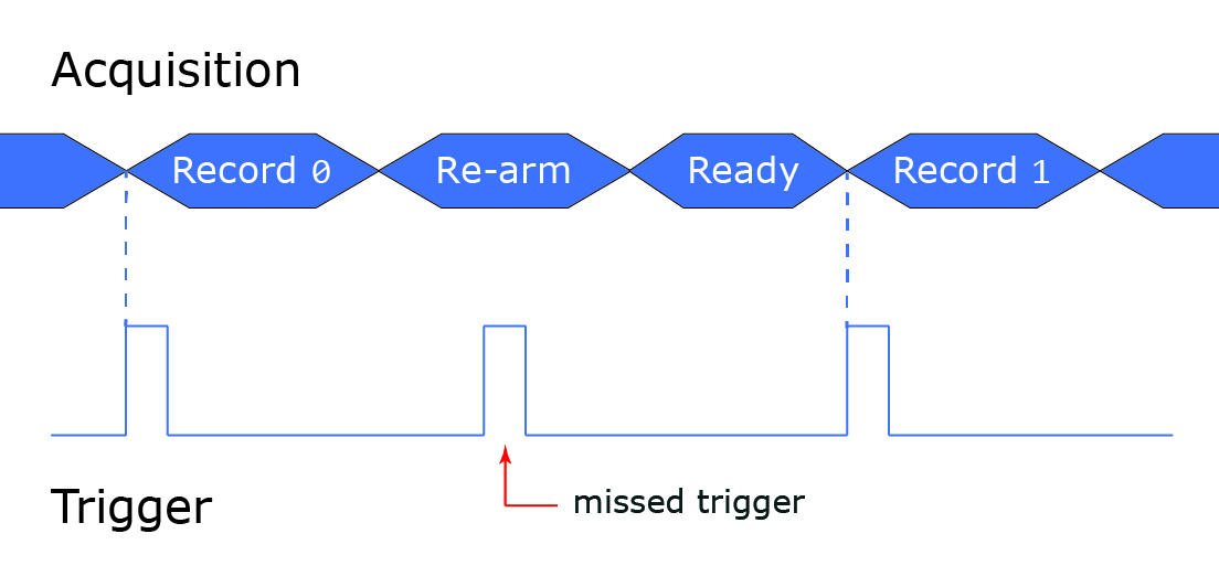
Figure 1 – Missed trigger during re-arm
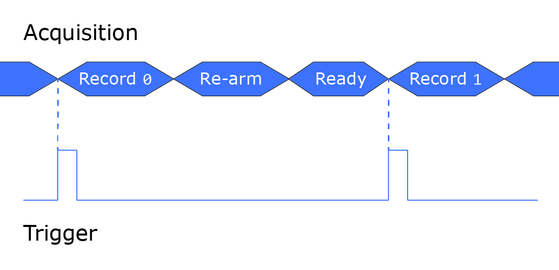
Figure 2 – Successful acquisition cycle with no missed triggers
Another reason why triggers are missed, is if a trigger happens while a record is being acquired. It’s important that triggers occur at the very beginning of each record acquisition, as demonstrated by the dotted line in each of the diagrams shown above.
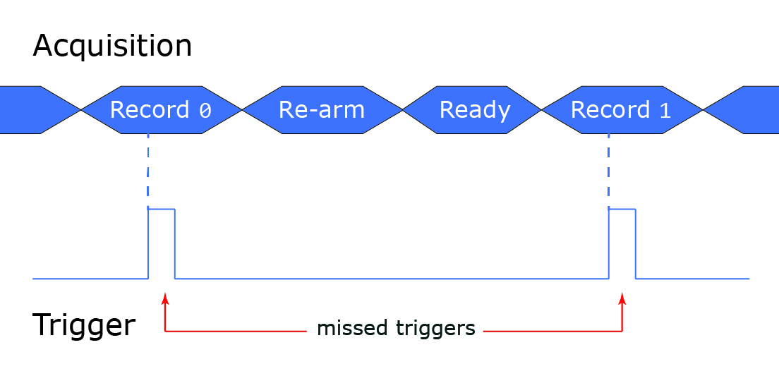
Figure 3 – Missed triggers during record acquisition
[1061] Is it possible to trigger an AlazarTech digitizer on both rising and falling edges of a signal?
Lien vers cette réponse: Copié
Yes, this is known as dual edge triggering. The AlazarSetTriggerOperation() API function can be used to activate both trigger engines. The process can be conducted in AlazarDSO, with the following settings applied:
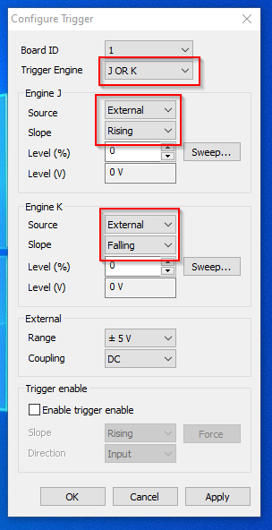
The following call to the C function AlazarSetTriggerOperation is an example of how dual edge triggering can be set up on external trigger:
RETURN_CODE rc = AlazarSetTriggerOperation(
boardHandle,
TRIG_ENGINE_OP_J_OR_K,
TRIG_ENGINE_J,
TRIG_EXTERNAL,
TRIGGER_SLOPE_POSITIVE,
128,
TRIG_ENGINE_K,
TRIG_EXTERNAL,
TRIGGER_SLOPE_NEGATIVE,
128);
A more detailed explanation on how to set up this operation is provided in the ATS-SDK manual, under the Trigger control section.
[1060] What’s the difference between various acquisition modes?
Lien vers cette réponse: Copié
At the root, there are two types of acquisition modes; single port and dual port.
Single port acquisition mode is in its own category. Data is acquired to on-board memory and then, after the acquisition is complete, transfers data from on-board memory to application buffers.
Dual port AutoDMA acquisition mode acquires to on-board memory while simultaneously transferring data from on-board memory to application buffers. This is the category under which all acquisition modes other than single port fall under. Dual port AutoDMA acquisition modes include:
- Traditional AutoDMA – This mode acquires multiple records, one per trigger event. Records may contain samples before and after their trigger event. Each buffer contains one or more records. A record header may optionally precede each record, and this mode supports low trigger repeat rates.
- No Pre-Trigger (NPT) AutoDMA – This acquisition mode acquires multiple records, one per trigger event. Some boards support a very limited number of pre-trigger samples. Otherwise, only post-trigger samples are possible. Each buffer contains one or more records, and this mode supports high trigger repetition rates.
- Triggered Streaming AutoDMA – In this acquisition mode, a single, gapless record spanning on or more DMA buggers is acquired. Each DMA buffer then contains only a segment of the record. This mode waits for a trigger event before acquiring the record.
- Continuous Streaming AutoDMA – Like Triggered Streaming AutoDMA, this acquisition mode acquires a single, gapless record spanning one or more DMA buffers, therefore each DMA buffer contains only one segment of the record. However, this mode does not wait for a trigger event before acquiring the record.
For a full explanation on how each of these acquisition modes work, consult the ATS-SDK manual.
[1059] What's the difference between the resolution of the board and bits per sample transferred?
Lien vers cette réponse: Copié
Data is transferred by default using 2 bytes per sample, and the actual ADC data is located in the most significant bits of each word. Samples are strictly assigned on byte boundaries, with 1 byte containing 8 bits. Due to these boundaries, samples are padded with 0s up to the next multiple of 8 bits, meaning that a board with a 12-bit resolution for example, is actually transferring 16 bits per sample.
Note that certain boards support data packing, a feature that eliminates byte boundaries. Using data packing, samples can start immediately instead of being padded up to the next byte. For a full explanation of this feature and supported boards, see our FAQ on data packing.
[1058] How can I get timestamp information for acquired records?
Lien vers cette réponse: Copié
To obtain data on the point in time when a record was acquired, you can use NPT footers, or in some cases, record headers, both of which contain timestamps.
NPT footers replace the last 16 bytes of each record with a footer structure containing timestamp information. For ATS9416, ATS9373, ATS9371, and ATS9360, you must use NPT footers for timestamp information.
In Traditional AutoDMA, record headers can be used. Record headers are 16-byte structures that precede a given record, and contain timestamp information for the following record. However, this setting can only be enabled for board with on-board memory, and thus support Traditional AutoDMA.
For more detailed instructions on how to use NPT footers and record headers, see the ATS-SDK guide.
[1057] Can I install ATSApi without having a board installed in my computer?
Lien vers cette réponse: Copié
ATSApi can be installed for specific cases where customers need to acquire samples on a computer other than the one in which an AlazarTech board is installed. Installing ATSApi.dll will allow users to run applications without getting a “missing dll” error due to a missing board.
Note: ATSApi does not support a simulation mode. Users will not be able to run acquisitions without actual hardware installed in the computer.
In order to install ATSApi without having a board installed in your computer, please contact support.
[1056] What is the difference between records and buffers, and what are records per buffer?
Lien vers cette réponse: Copié
A record is a group of samples acquired following a trigger event. In triggered acquisition modes (e.g. NPT, Traditional) the acquisition of a record follows a trigger event, and multiple records are packed into each buffer that’s transferred to the host computer. In continuous acquisition modes (e.g. continuous, streaming) the entire acquisition consists of one long record, which is then split up into multiple buffers for data transfer.
Buffers or DMA buffers are “packets” of data sent from AlazarTech digitizers’ on-board memory to the host computer’s RAM. Each time the application calls up the AlazarWaitNextAsyncBufferComplete function, it retrieves a DMA buffer from the board and copies the data so it’s ready to be consumed.
The number of records per buffer indicates how many triggers worth of data are present in each DMA buffer transferred to the host computer’s RAM.
For a more detailed explanation of records and buffers, click here.
It should be noted that the number of records per buffer has no impact on data acquisition. This only defines how records are grouped for transfer. For best performance, we recommend users select values of records per buffer that result in DMA buffers between 1 MB and 8 MB.
[1055] What are the differences among programming languages when interfacing to ATSApi?
Lien vers cette réponse: Copié
The most significant difference pertains to LabVIEW. LabVIEW’s memory model prevents user applications from interacting with memory that has been used to perform DMA transfers. Essentially, this means the data acquired by AlazarTech boards must be copied into a “LabVIEW memory buffer” in order for LabVIEW code samples to access it. This process of copying memory can be costly, and limits the maximum throughput of data to LabVIEW applications from AlazarTech boards to approximately 1.5 GB/s (depending on the computer and configuration).
Other programming languages, such as Python, MATLAB, and C/C++/C# allow user applications access to memory, so these applications can run at higher data rates.
[1054] Why is the "Dual-ported memory" option disabled in the Stream to Memory wizard?
Lien vers cette réponse: Copié
The "dual-ported memory" option is disabled for boards that instead use on-board memory that acts as a very deep FIFO. Rather than using dual-ported memory, these boards acquire data while at the same time transferring previously acquired data to the PC. Boards that use on-board memory as a very deep FIFO include: ATS9373, ATS9371, ATS9360, and ATS9416
[1052] Why is the “Multiple records with pre-trigger samples (Traditional)” option disabled in the Stream to Memory wizard?
Lien vers cette réponse: Copié
The multiple records with pre-trigger samples (Traditional) setting corresponds to an acquisition mode known as Traditional AutoDMA. However, this option is disabled for some AlazarTech digitizers which do not support Traditional AutoDMA. Boards that do not support Traditional AutoDMA include: ATS9373, ATS9371, ATS9360, and ATS9416
[1051] How to upgrade the FPGA Firmware on a PCIe digitizer board on a Linux operating system using AlazarTech Firmware Updater version 3.0 and above.
Lien vers cette réponse: Copié
Note: The following instructions have been created using CentOS. Users with other linux distributions may have different on-screen instructions to follow, as well as a different interface.
- Go to AlazarTech's website and choose your board from the PRODUCTS drop-down menu
- Down on the product’s page, from the Drivers section:
- Click on Linux Resources. From here, select your CPU type to see the available resources.
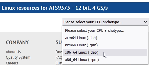
Then, download the Firmware Update Utility.
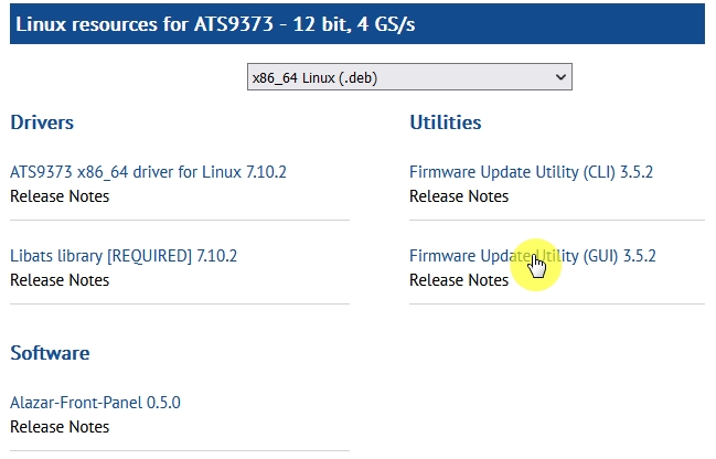
Note 1: The following instructions have been created for the graphical user interface (GUI) variation of the firmware updater as it is recommended for most users. To install the command-line interface (CLI) variation, download fwupdater-CLI-x.x.x instead.
Note 2: Running fwupdater-CLI may cause a segmentation fault; Under Linux, fwupdater-CLI links to system libraries in order to run. If users do not have execute permission on these libraries, they may get a segmentation fault when trying to run fwupdater-CLI. A workaround to this issue would be to run the fwupdater-CLI with elevated privileges or to change the permissions on these libraries.
2. Click on ATSxxxx Firmware to download the firmware file – e.g. ATS9373-A3 Firmware
- Unarchive the firmware file. Make sure that the Linux Driver is installed on this computer. Also make sure that all other applications using this driver or the ATSApi Library are closed (E.g.: AlazarFrontPanel).
- Run the firmware updater fwupdater-GUI-x.x.x.yyy (where x.x.x is the firmware updater version number and yyy is the distribution).
- Click the blue Install button to begin the process.
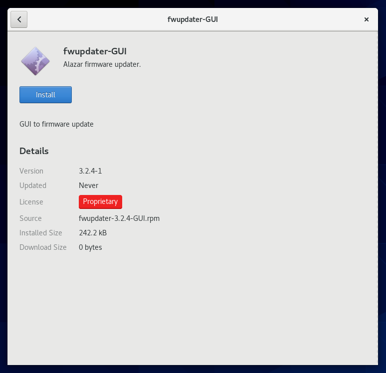
- Once the firmware updater is installed, you can start it from the Alazar Firmware Updater start menu item, or by pressing the start button and typing Firmware Updater.
- When you start AlazarTech Firmware Updater, you will see the following:
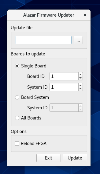
- In Update file, click on the ellipsis to choose the corresponding firmware (.pof file) you previously downloaded.
- Select the board(s) that you wish to update. If you have only one board installed in the computer, you can leave the Boards to update section unmodified. The options available are:
- Single Board Only: Updates one digitizer in the system. The digitizer to update is selected with the Board ID and System ID fields.
- Boards System: Updates all the boards in a system. The boards system is selected with the System ID field.
- All Boards: Updates all the boards in the computer
- Once all the parameters are set properly, click UPDATE to start the FPGA update. A window will appear to indicate the progress of this process.
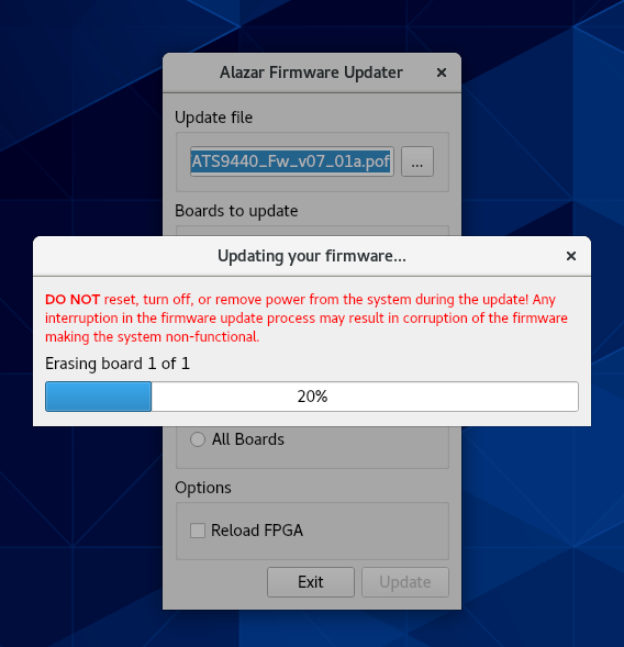
Warning: Some versions of ATS9373 require advanced settings to be configured for the update to succeed. See FAQ 1040 for more information.
- After the update is complete, you will see a window indicating that the update was successful. You should shut down, then turn on the computer.
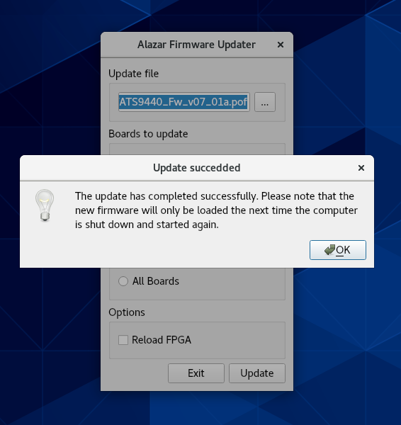
- You can then confirm that the update worked:
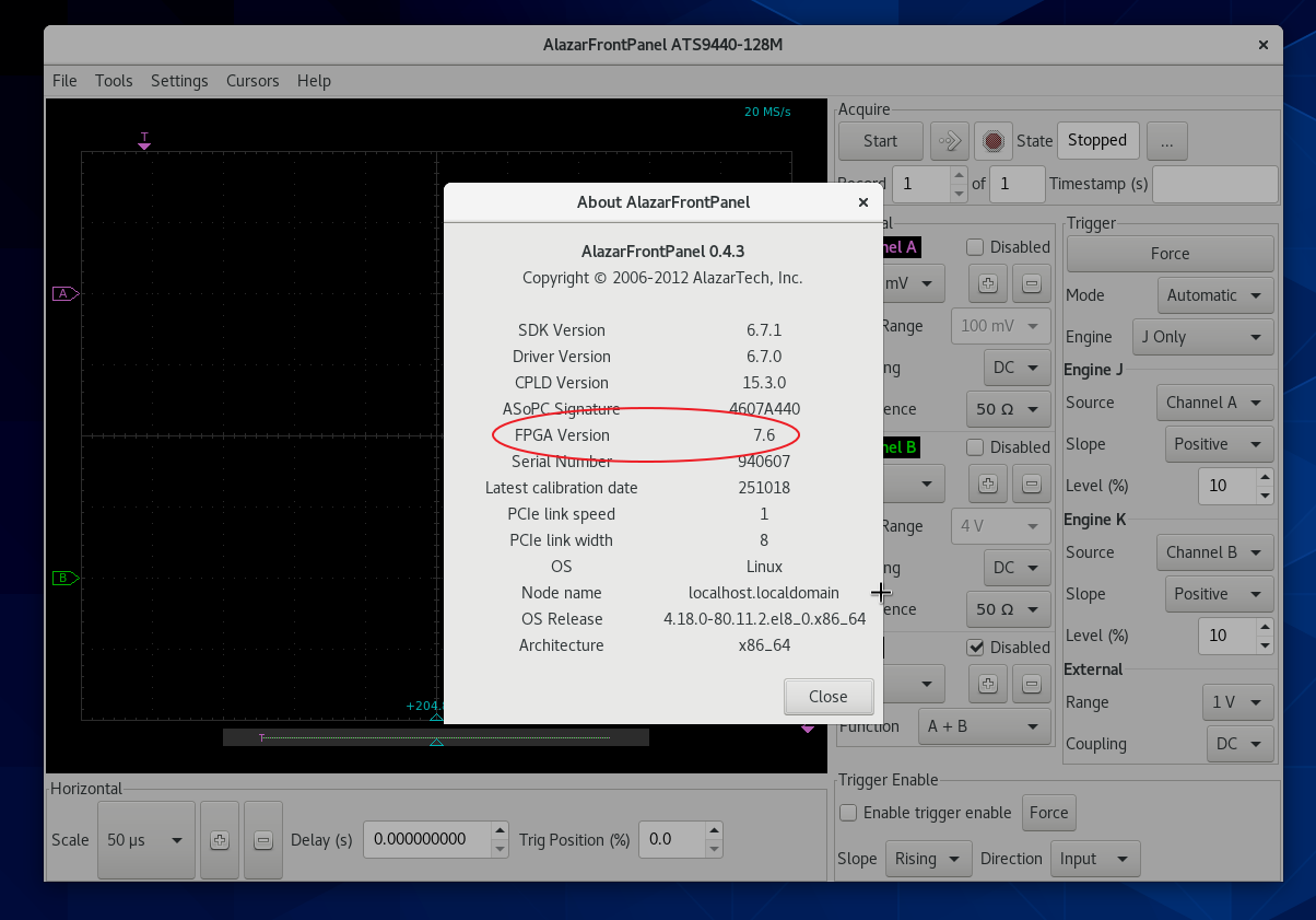
- Run AlazarFrontPanel software
- Next, click Help and then select About from the drop-down menu that follows.
This will display an About AlazarFrontPanel pop-up. - One of the lines is FPGA version. Make sure the version number displayed corresponds to the version of the FPGA you downloaded (.exe file name).
[1050] How to upgrade the FPGA Firmware on a PCIe digitizer board on a computer running Windows OS using AlazarTech Firmware Updater version 3.0 and above.
Lien vers cette réponse: Copié
If you have been instructed to use Firmware Updater 2.0.9 or older, please click here for the FAQ specific to the older Firmware Updater.
- Go to AlazarTech's website and choose your board from the PRODUCTS drop-down menu
- Down on the product`s page, from the Software section:
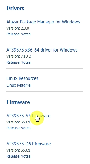
1. download the Firmware Update Utility
2. download the Firmware file – E.g.: ATS9373-A3 Firmware - Unarchive both files. Make sure that the Windows Driver is installed on this computer. Also make sure that all other applications using this driver or ATSAPI.dll are closed (E.g.: AlazarDSO).
- Run the executable file fwupdater-x.x.x.exe (where x.x.x is the firmware updater version number) to install AlazarTech Firmware Updater.
- Click NEXT
- You must Agree to the License Agreement in order to proceed
- Select your Install Options and click NEXT
- Select your Installation Location and click NEXT
- Select your Start Menu Folder and click NEXT
- Select your Components and click NEXT. AlazarTech Firmware Updater 3.0+ comes in two forms: a graphical user interface (GUI), which is recommended for most users, and a command line interface (CLI) that is more appropriate for OEMs and advanced users.
- Click FINISH to complete the installation. Once the firmware updater is installed, you can start it from the AlazarTech Firmware Updater start menu item, or by pressing the start button and typing Firmware Updater.
- When you start AlazarTech Firmware Updater, you will see the following:
In Update file, click on the ellipsis to choose the corresponding firmware (.pof file) you previously downloaded. - Select the board(s) that you wish to update. If you have only one board installed in the computer, you can leave the Boards to update section unmodified. The options available are:
- Single Board Only: Updates one digitizer in the system. The digitizer to update is selected with the Board ID and System ID fields.
- Boards System: Updates all the boards in a system. The boards system is selected with the System ID field.
- All Boards: Updates all the boards in the computer
- Once all the parameters are set properly, click UPDATE to start the FPGA update. A window will appear to indicate the progress of this process.
Warning: Some versions of ATS9373 require advanced settings to be configured for the update to succeed. See FAQ 1040 for more information.
- After the update is complete, you should power cycle the computer. You can then confirm that the update worked:
- Run AlazarDSO software
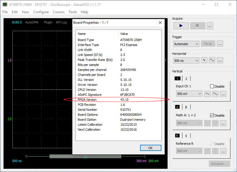
- Press F4 key. It will display the Board Properties page. One of the lines is FPGA version. Make sure the version number displayed corresponds to the version of the FPGA you downloaded (.exe file name).
[1049] My AlazarTech digitizer seems to have failed. The fan is not spinning but almost all the LEDs are lit or blinking, with the exception of "FPGA".
Lien vers cette réponse: Copié
The PS1, PS2 and PS3 red LEDs being lit are indications that power supplies have failed on the board. Follow the steps in this flowchart:
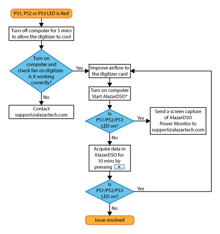
Note that depending on your board, power monitor status LEDs may be labeled as:
LED2, LED10, LED11, LED12, LED13, LED14, or LED15.
Check your AlazarTech product's manual for identification of all status LEDs on your specific board.
For instructions on accessing Power Monitor in AlazarDSO:
https://www.alazartech.com/Support/Faq?se=1045
[1048] How do I distinguish between buffers and records?
Lien vers cette réponse: Copié
Buffers are the unit of data transfer between the digitizer board and the host application. They are allocated by the user (AlazarAllocBuffer[U8\U16]), posted to the board to get "filled" with data (AlazarPostAsyncBuffer) and then retrieved (AlazarWaitAsyncBufferComplete).
Records on the other hand are series of samples acquired continuously. In triggered acquisition modes (NPT, Traditional), the acquisition of a record follows a trigger event and multiple records are packed into each buffer that gets transferred to the host computer. In the continuous acquisition modes (Continuous streaming), the whole acquisition consists of only one long record, that gets split up into multiple buffers for data transfer.
[1047] I can not set the external trigger to AC coupling on my ATS9870. Setting the ExternalTrigger to AC coupling results in an ApiNotSupportThisChannel error.
Lien vers cette réponse: Copié
The error that you get is normal. AC coupling is not available on ATS9870. Early versions of ATS9870 (sold before 2010) supported AC coupling on the external trigger, but this feature was dropped in favor of high impedance support on this port.
[1046] I am having trouble detecting my new ATS9373 digitizer in my computer, a Dell Precision 5820 with an Intel Xeon W-2125 processor. The digitizer does not show up under PCI devices in the BIOS, or under Device Manager. I have the latest drivers installed. I have tried the digitizer in a colleague's Supermicro workstation with an Intel Xeon W processor and I was able to detect the board. Have you run into this issue before?
Lien vers cette réponse: Copié
Dell Precision T58x0 and T79xx both had a known BIOS bug 2 years ago, whereby it could not detect PCIe Gen3 boards due to the way the PCIe lanes were grouped in the BIOS. Gen2 and Gen1 boards were detected without any problems. The ATS9373 and ATS9371 are PCIe Gen3 boards.
This bug was fixed in the summer of 2016 and the updated BIOS was released on Dell’s website. Please update the BIOS for your computer to the latest version available on Dell’s website.
Another possible reason for the digitizer not being detected is that some of the PCIe slots in your computer may not be functional. If you have a 28-lane CPU in your motherboard instead of a 44-lane CPU, some of your PCIe slots will not be functional. This may or may not be documented in your computer's hardware manual. You should try installing the digitizer in a different PCIe slot.
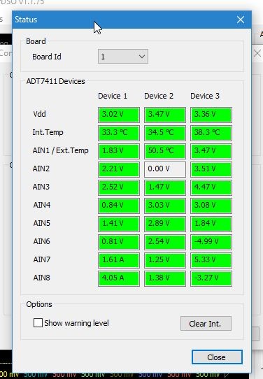
[1045] I see that PCI Express based AlazarTech A/D boards monitor many on-board voltages and currents and this health-check data is available in Power Monitor. How do I run Power Monitor on my board?
Lien vers cette réponse: Copié
1. Start AlazarDSO, and go to "Configure | Plugins"
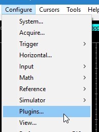
2. Check "Enable plugins", select "Power Monitor" and click "Configure"
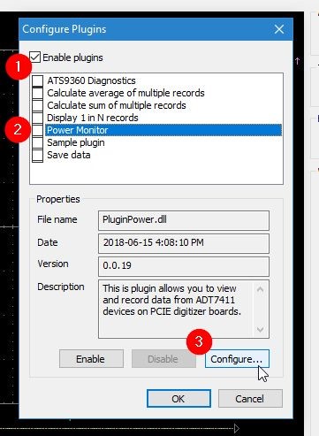
3. Click "Status..."
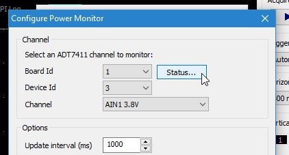
4. Send us a screenshot of the "Status" window that appears
[1044] I am using ATS9373 to acquire signals on two channels. The buffers I receive contain interleaved data R0[ABABAB]R1[ABABAB]...Rn[ABABAB]. De-interleaving takes quite a bit of time. Is there any way I can get de-interleaved data in my buffers? I also tried ATS9371 and it behaves the same way.
Lien vers cette réponse: Copié
By default, ATS9373 and ATS9371 deliver dual channel data in interleaved mode, i.e. R0[ABABAB]R1[ABABAB]...Rn[ABABAB].
The good news is that we have recently modified the ATS9373 and ATS9371 firmware to allow you to ask for de-interleaved data: CH A and CH B data comes out in alternating buffers. We call it “Dual Buffer Mode”. In other words, The Dual Buffer mode outputs data from the two acquired channels in two consecutive DMA buffers.
You will have to update the firmware on your board to the latest version. Please consult the appropriate product page:
There is a simple API that can be used to select Dual Buffer mode.
First, you must determine if the board you have is capable of doing Dual Buffer Mode. To do this, you must call AlazarQueryCapability with the HAS_DUAL_BUFFER_SUPPORT parameter. Note that HAS_DUAL_BUFFER_SUPPORT = 0x10000072UL. AlazarQueryCapability then checks if you have the right board type (ATS9373 or ATS9371) and the right firmware (> v28.02). The call will return 1 if the feature is supported, and 0 otherwise.
U32 dualBufferSupport; printf("Dual-buffer mode is %s.", (dualBufferSupport) ? "supported" : "not supported"); |
If the feature is supported, the only change you need to make is to add ADMA_DUAL_BUFFER_MODE to the flags of AlazarBeforeAsyncRead(). Note that ADMA_DUAL_BUFFER_MODE = 0x00020000.
Now, you will receive even buffers that are formatted as R0[AAAAAA]R1[AAAAAA]...Rn[AAAAAA] followed by odd buffers formatted as R0[BBBBBB]R1[BBBBBB]...Rn[BBBBBB].
[1043] Why does ATS-GPU not come with an installer for Windows 32-bit architecture?
Lien vers cette réponse: Copié
ATS-GPU does not support 32-bit Windows.
ATS-GPU only supports Windows versions and Linux distributions that are supported by NVIDIA’s CUDA Toolkit. Please refer to the latest ATS-GPU-BASE datasheet for the version of the CUDA Toolkit used in ATS-GPU.
Deployment and execution of CUDA applications on x86_32 architectures is extremely limited. The CUDA toolkit is supported only for particular GPUs and for old Visual C++ compilers. CUDA support for 32-bit architectures is likely to completely discontinue in a foreseeable future. ATS-GPU 4.0.0, therefore, stopped support for 32-bit architectures.
[1042] I tried to install AlazarTech Linux drivers and the installation failed with a "Required key not available" error. What should I do?
Lien vers cette réponse: Copié
Ubuntu with kernels 4.4.0-20 and above uses a kernel configuration entry that prevents the installation of third party drivers [1].
If this kernel configuration is active and the secure boot option is enabled in your computer's UEFI BIOS, the installation of AlazarTech drivers will fail. To check the state of the kernel configuration, you can use the "mokutil --sb-state" command [2].
The workaround is to either disable secure boot in the BIOS or to use "mokutil --disable-validation" [1].
[1041] I am trying to install AlazarTech drivers on a Windows 7 computer and it is not working. Are your boards compatible with Windows 7?
Lien vers cette réponse: Copié
AlazarTech boards and their drivers are fully compatible with Windows 7 SP1 with a security update KB3033929 or later. This security update allows Windows 7 drivers to use the same 256 bit encryption that Windows 10 uses. AlazarTech drivers version 6.03+ use 256 bit encryption to be fully compatible with Windows 10, Windows 8.x and Window7 SP1 with security update. Older drivers did not use 256 bit encryption.
You must use drivers version 6.1.2 or higher for this installation to work properly on a properly configured Windows 7 machine.
Prior driver versions (v6.0.3, v6.1.0 and v6.1.1) tried to interrogate the system to make sure that this particular security update is installed before installing the driver. Unfortunately, the operating system reports only the latest update, which may be different than KB3033929, even though KB3033929 has been installed. This caused our installation program to think that the security update had not been installed and the installation would fail.
We have determined that there is no programmatic method of determining whether the security update has been installed or not. Driver versions 6.1.2 and later no longer check for this update. This allows the drivers to be installed correctly.
Note that it is the user’s responsibility to make sure the latest security update is installed.
If the required security update is not installed on the target computer running Windows 7, installation of driver version 6.1.2 or higher will fail with the following error messages:
When Installing drivers 6.1.2 on a Windows 7 machine without service pack 1 (SP1):
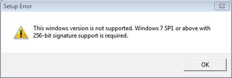
When Installing the drivers on a Windows 7 SP1 machine without the Windows security update KB3033929:
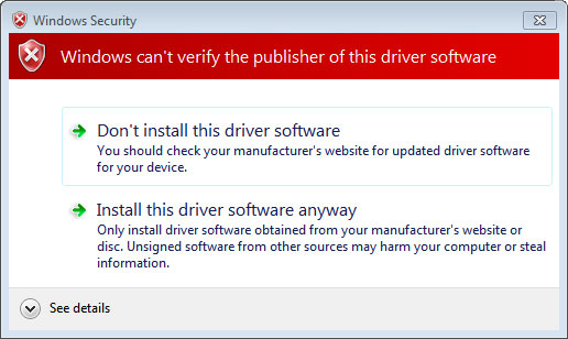
Installing the drivers anyway will generate the following message shortly thereafter because security update KB3033929 is required for Windows to understand the driver signing used by our drivers:
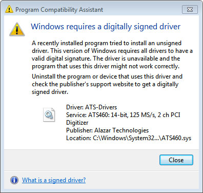
To resolve this problem, make sure SP1 is installed and the latest security update for Windows 7 is also installed.
[1040] How do I update the firmware on the ATS9373? I tried to update the firmware, and according to the log file, the firmware update was successful. However, when I run AlazarDSO and check the firmware version, it shows that I am using the old firmware.
Lien vers cette réponse: Copié
The updated firmware is most likely on a different flash memory page, which is not being accessed.
There are two pages of flash memory on the ATS9373. Usually, the board loads up from page 0. Page 1 is a fallback (factory default) image that is to be used if loading from page 0 fails.
In some computers, ATS9373 always loads from page 1, i.e. the attempted load from page 0 fails due to power sequencing issues. This may be the case on your computer.
To update the second flash page using Firmware Updater version 3.2.0 or later, please follow these instructions:
1. Start Alazar Firmware Updater
2. Select the firmware (.pof) file by either
- Clicking on the ellipsis button
 to navigate to the file,
 - Entering the path manually in the text box,
- Dragging a file directly into the text box.
Note: If there is only one file with the .pof extension present on your desktop when the firmware updater starts, it will be selected by default as the firmware with which to update your board.
3. Next, you should select the board(s) that you wish to update. If you have only one board installed in the computer, you can leave the Boards to update section unchanged.
4. Before clicking on Update, press <Ctrl-F5>. This will pop up the Advanced Options page.
5. On the Advanced Options page, uncheck Auto-select Pages, check Write Page 0 and check Write Page 1 as shown below:
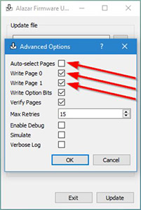
6. Click OK to get back to the main Alazar Firmware Updater page
7. Click Update
8. Let the firmware update continue. A window will appear to indicate the progress of this process.
9. Turn off the computer
10. Turn computer back on. Note: A full power cycle is required for the new firmware version to get loaded. A simple restart is not enough.
11. In Windows, run AlazarDSO, press <F4>, and verify that the FPGA Version reported is the one you uploaded.
In Linux, run AlazarFrontPanel and go to the Help menu. Select About to display the AboutAlazarFrontPanel window, and verify that the FPGA Version reported is the one you uploaded.
[1039] I used one of your sample programs to develop my own program for my ATS9373. When I run my program, the acquired data has a huge offset. However, if I run AlazarDSO before running my program, this problem disappears and the acquired data is good. I don’t want to have to run AlazarDSO before my program. How can I fix this problem?
Lien vers cette réponse: Copié
There was a bug in one of our drivers that caused the on-board flash memory not to be read correctly when the driver is loaded. As such, all input offsets and gains were not set correctly.
AlazarDSO used a backdoor method to read the flash memory correctly. That is why it was able to set the offsets properly. And once AlazarDSO had read these correct values, your program was also able to use those correct values and the acquired data was good.
This issue affected the ATS9373, ATS9360 & ATS9416, and was fixed in driver 5.10.19 and later versions, i.e. the driver reads the flash memory properly upon startup.
Please update your driver and DLL to the latest version to correct this issue. You can find the latest drivers on the product page of the affected product (ATS9373, ATS9360, ATS9416)
[1036] I just downloaded ATS-SDK v7.1.5 and I cannot compile the example programs that come with it. AlazarInputControlEx returns an error on my system. Previous versions of ATS-SDK work just fine. Why?
Lien vers cette réponse: Copié
AlazarInputControlEx is a superset to AlazarInputControl which allows to address boards with more than 8 channels. Version 7.1.5 uses this function by default on all boards, but it is only fully supported with library 5.10.14 and above. To solve the error, the recommended solution is to update your library (DLL) to 5.10.14 or above. If updating is not an option, you can replace calls to AlazarInputControlEx with AlazarInputControl. Please note that all errors relating to unsupported parameters (input range, impedance) will still appear irrespective of which function you use.
[1035] Where can I find the hardware or PCB version number for my ATS9373?
Lien vers cette réponse: Copié
In the recent versions of the ATS9373, PCB V1.1 or later, it is possible to read PCB version number via software.
In AlazarDSO software, Press F4 to open up the Board Properties window. PCB revision number is displayed as shown below: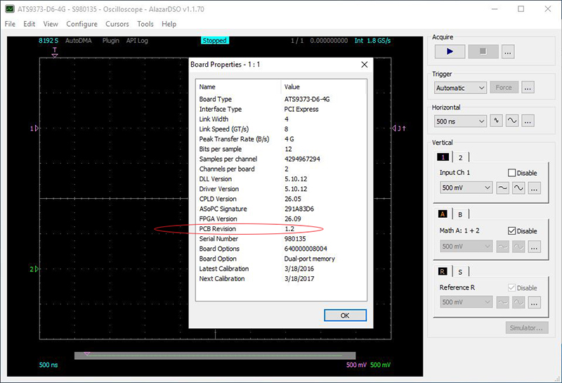
User software can also read this version number using AlazarGetBoardRevision API call. Note that older versions of PCB that do not support this feature will return PCB Revision number as 1.15 (0xF).
In all cases, the PCB version is silkscreened on the circuit board as shown here: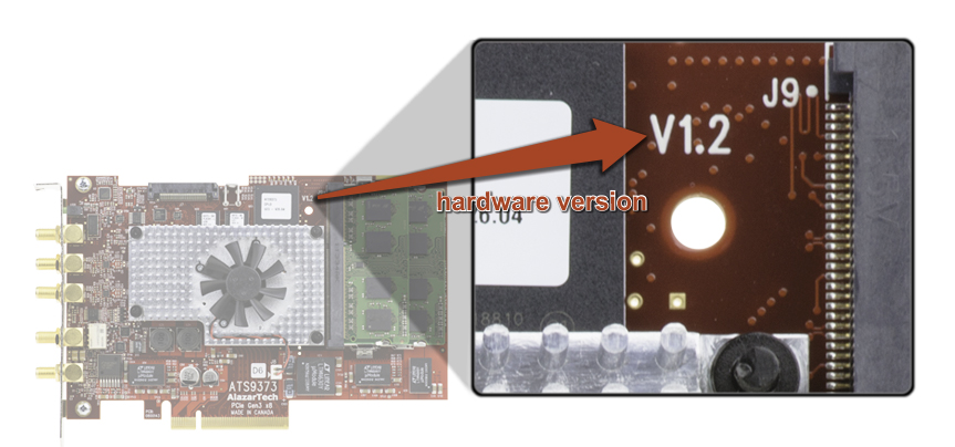
[1034] Where can I find the hardware or PCB version number for my ATS9360?
Lien vers cette réponse: Copié
In the recent versions of the ATS9360, PCB V1.2 or later, it is possible to read PCB version number via software.
In AlazarDSO software, Press F4 to open up the Board Properties window. PCB revision number is displayed as shown below: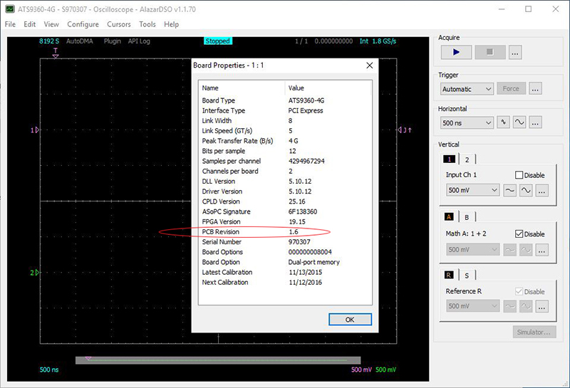
User software can also read this version number using AlazarGetBoardRevision API call. Note that older versions of PCB that do not support this feature will return PCB Revision number as 1.15 (0xF).
In all cases, the PCB version is silkscreened on the circuit board as shown here: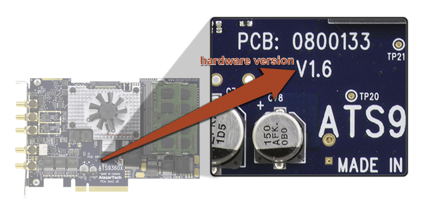
[1033] Where can I find the hardware or PCB version number for my ATS9870?
Lien vers cette réponse: Copié
In the recent versions of the ATS9870, PCB V1.6 or later, it is possible to read PCB version number via software.
In AlazarDSO software, Press F4 to open up the Board Properties window. PCB revision number is displayed as shown below: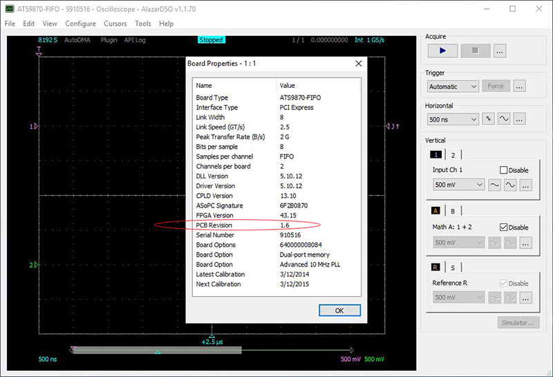
User software can also read this version number using AlazarGetBoardRevision API call. Note that older versions of PCB that do not support this feature will return PCB Revision number as 1.15 (0xF). In all cases, the PCB version is silkscreened on the circuit board as shown here: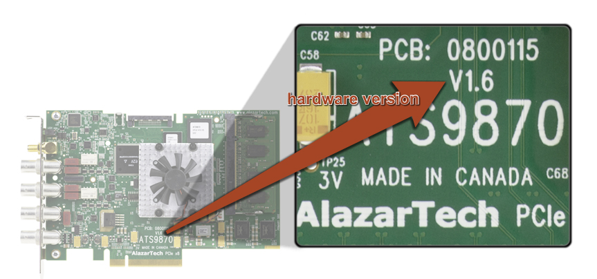
[1032] Where can I find the hardware or PCB version number for my ATS9350?
Lien vers cette réponse: Copié
In the recent versions of the ATS9350, PCB V1.7 or later, it is possible to read PCB version number via software.
In AlazarDSO software, Press F4 to open up the Board Properties window. PCB revision number is displayed as shown below: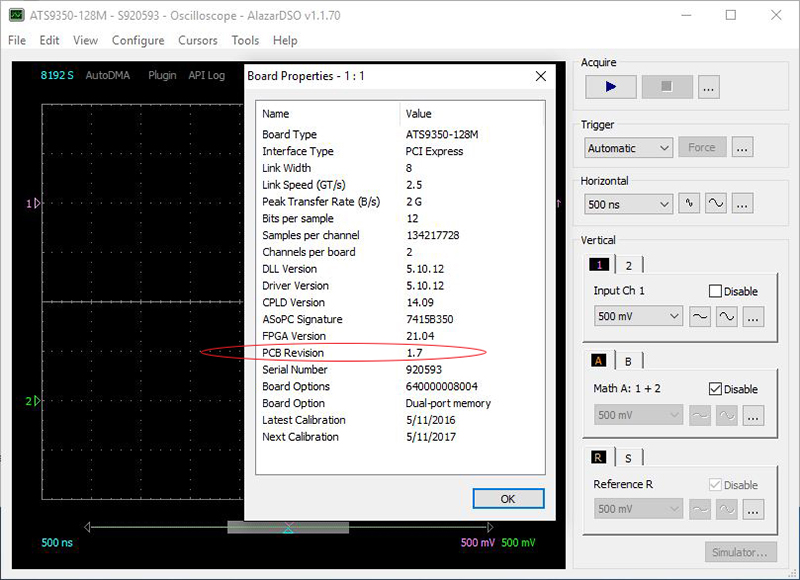
User software can also read this version number using AlazarGetBoardRevision API call. Note that older versions of PCB that do not support this feature will return PCB Revision number as 1.15 (0xF).
In all cases, the PCB version is silkscreened on the circuit board as shown here: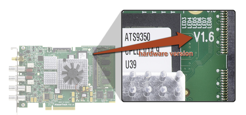
[1031] Where can I find the hardware or PCB version number for my ATS9351?
Lien vers cette réponse: Copié
In the recent versions of the ATS9351, PCB V1.9 or later, it is possible to read PCB version number via software.
In AlazarDSO software, Press F4 to open up the Board Properties window. PCB revision number is displayed as shown below: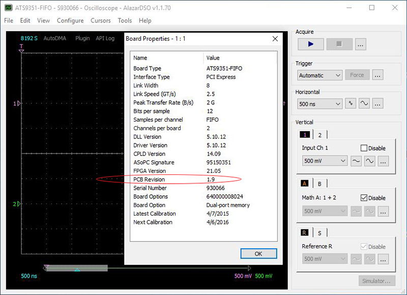
User software can also read this version number using AlazarGetBoardRevision API call. Note that older versions of PCB that do not support this feature will return PCB Revision number as 1.15 (0xF).
In all cases, the PCB version is silkscreened on the circuit board as shown here: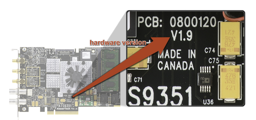
[1030] Where can I find the hardware or PCB version number for my ATS9625?
Lien vers cette réponse: Copié
In the recent versions of the ATS9625, PCB V1.2 or later, it is possible to read PCB version number via software.
In AlazarDSO software, Press F4 to open up the Board Properties window. PCB revision number is displayed as shown below: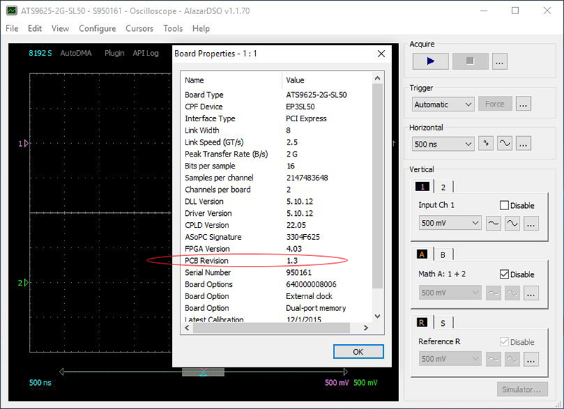
User software can also read this version number using AlazarGetBoardRevision API call. Note that older versions of PCB that do not support this feature will return PCB Revision number as 1.15 (0xF).
In all cases, the PCB version is silkscreened on the circuit board as shown here: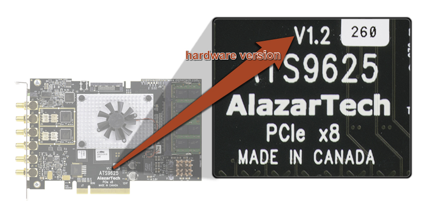
[1029] Where can I find the hardware or PCB version number for my ATS9626?
Lien vers cette réponse: Copié
In the recent versions of the ATS9626, PCB V1.1 or later, it is possible to read PCB version number via software.
In AlazarDSO software, Press F4 to open up the Board Properties window. PCB revision number is displayed as shown below: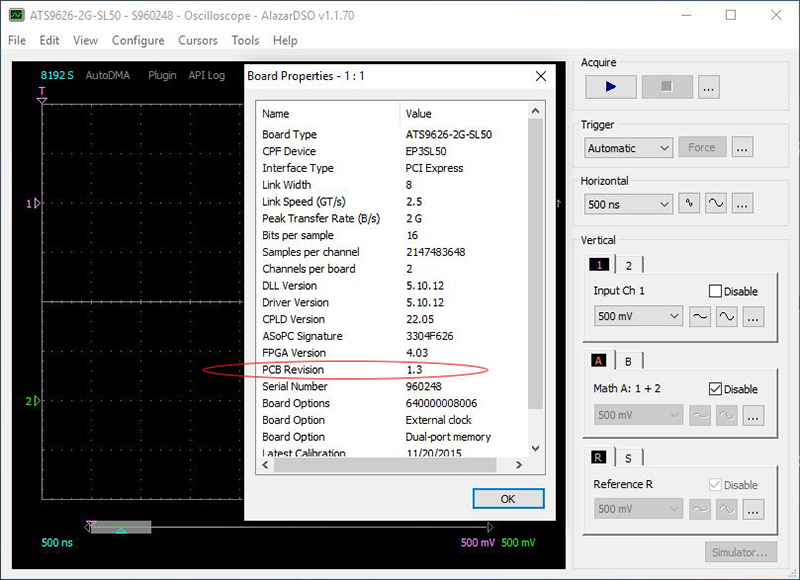
User software can also read this version number using AlazarGetBoardRevision API call. Note that older versions of PCB that do not support this feature will return PCB Revision number as 1.15 (0xF).
In all cases, the PCB version is silkscreened on the circuit board as shown here: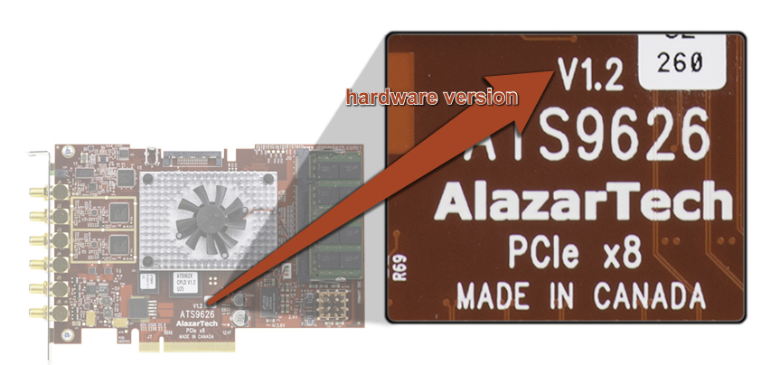
[1028] Where can I find the hardware or PCB version number for my ATS9462?
Lien vers cette réponse: Copié
Where can I find the hardware or PCB version number for my ATS9462? In the recent versions of the ATS9462, PCB V1.5 or later, it is possible to read PCB version number via software.
In AlazarDSO software, Press F4 to open up the Board Properties window. PCB revision number is displayed as shown below: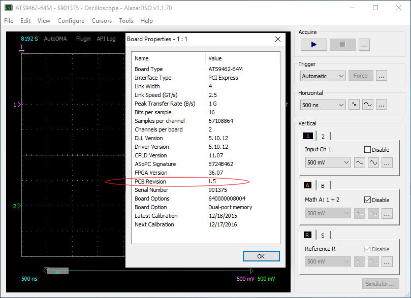
User software can also read this version number using AlazarGetBoardRevision API call. Note that older versions of PCB that do not support this feature will return PCB Revision number as 1.15 (0xF).
In all cases, the PCB version is silkscreened on the circuit board as shown here: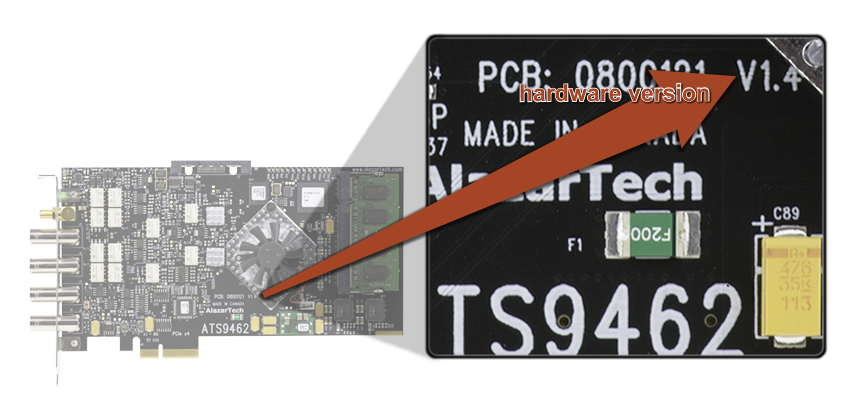
[1027] Where can I find the hardware or PCB version number for my ATS9440?
Lien vers cette réponse: Copié
Where can I find the hardware or PCB version number for my ATS9440? In the recent versions of the ATS9440, PCB V1.3 or later, it is possible to read PCB version number via software.
In AlazarDSO software, Press F4 to open up the Board Properties window. PCB revision number is displayed as shown below: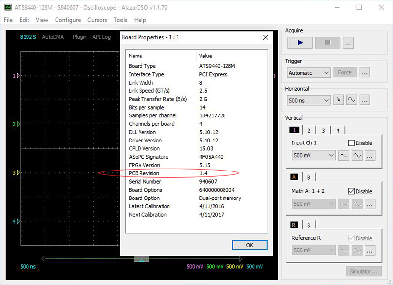
User software can also read this version number using AlazarGetBoardRevision API call. Note that older versions of PCB that do not support this feature will return PCB Revision number as 1.15 (0xF).
In all cases, the PCB version is silkscreened on the circuit board as shown here: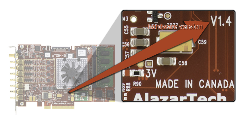
[1026] Where can I find the hardware or PCB version number for my ATS9416?
Lien vers cette réponse: Copié
In the recent versions of the ATS9416, PCB V1.0 or later, it is possible to read PCB version number via software.
In AlazarDSO software, Press F4 to open up the Board Properties window. PCB revision number is displayed as shown below: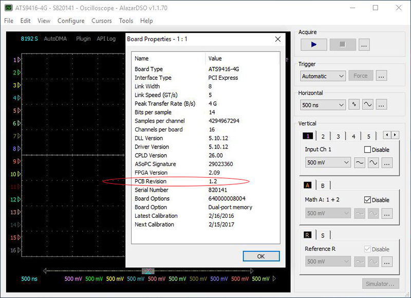
User software can also read this version number using AlazarGetBoardRevision API call. Note that older versions of PCB that do not support this feature will return PCB Revision number as 1.15 (0xF).
In all cases, the PCB version is silkscreened on the circuit board as shown here: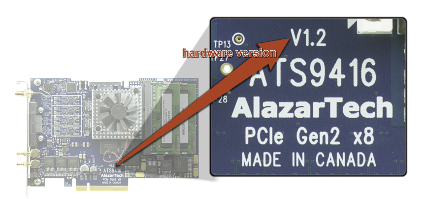
[1025] Where can I find the hardware or PCB version number for my ATS660?
Lien vers cette réponse: Copié
PCB version for ATS660 waveform digitizer board is silkscreened on the circuit board as shown below: 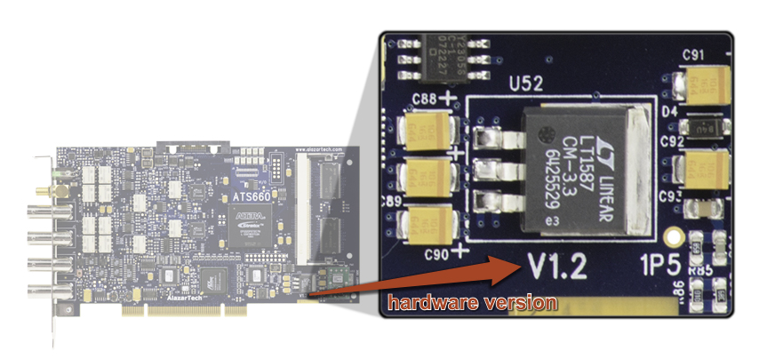
[1024] Where can I find the hardware or PCB version number for my ATS460?
Lien vers cette réponse: Copié
PCB version for ATS460 waveform digitizer board is silkscreened on the circuit board as shown below: 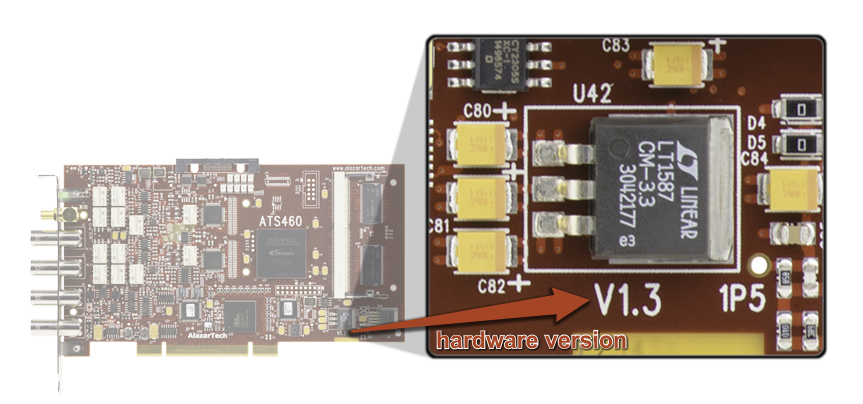
[1023] Where can I find the hardware or PCB version number for my ATS330?
Lien vers cette réponse: Copié
PCB version for ATS330 waveform digitizer board is silkscreened on the circuit board as shown below: 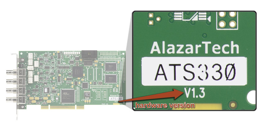
[1022] Where can I find the hardware or PCB version number for my ATS310?
Lien vers cette réponse: Copié
PCB version for ATS310 waveform digitizer board is silkscreened on the circuit board as shown below: 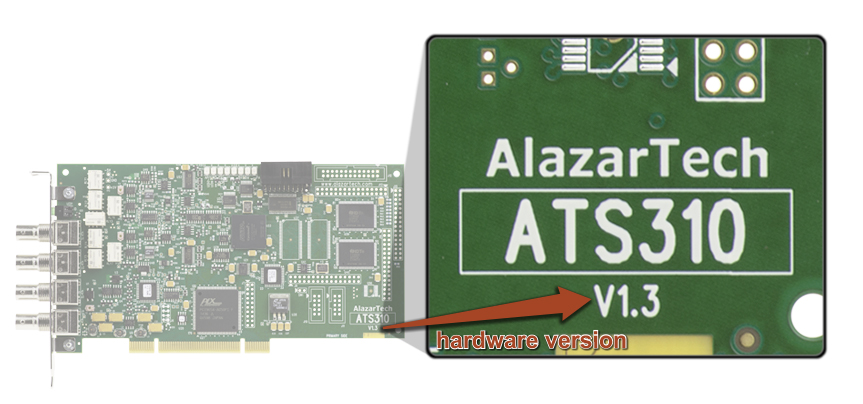
[1021] Where can I find the hardware or PCB version number for my ATS860?
Lien vers cette réponse: Copié
PCB version for ATS860 waveform digitizer board is silkscreened on the circuit board as shown below: 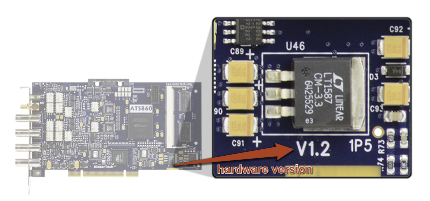
[1020] Where can I find the hardware or PCB version number for my ATS850?
Lien vers cette réponse: Copié
PCB version for ATS850 waveform digitizer board is silkscreened on the circuit board as shown below: 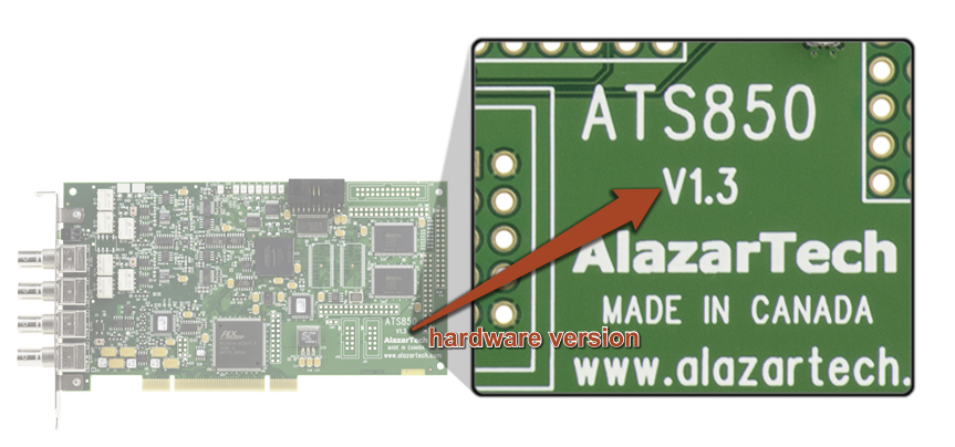
[1019] I have a few ATS460 boards that we have bought in the past. Can I use them as one Master/Slave system using a SyncBoard? Two of the boards have 128M memory and one has 8M memory.
Lien vers cette réponse: Copié
The requirements for being able to synchronize multiple boards in Leader/Follower mode are:
- All boards must have the same amount of memory
- All boards must have the same hardware version
You may be able to use the two ATS460-128M boards in Leader/Follower configuration, as long as they are of the same hardware version. Hardware version number is silkscreened on the printed circuit board. 
This FAQ has been modified to use more inclusive terminology. We are working on updating M/S multi-board systems to the new term Leader/Follower throughout our product documentation.
[1018] What does "screened" mean? We would like to know why it is introduced in this card, what it does, and what may happen without this option. Does this option (ATS9360-006 or ATS9373-006) includes the option -005 External Clock Upgrade?
Lien vers cette réponse: Copié
The ADCs used on ATS9360 and ATS9373 have a “minimum clock frequency” specification of 300 MHz, i.e. if the external clock signal is lower than 300 MHz, the ADC may not be able to make proper measurement. Typical problem is that user will see glitches in the output data. Many customer applications need the ATS9360 or ATS9373 to work with external clock frequencies lower than 300 MHz.
Fortunately, we have seen that many ATS9360 work perfectly down to 70 MHz clock rate.Similarly, many ATS9373 boards work perfectly down to 100 MHz external clock rate. We have developed a process by which we can “screen” the board for external clock operation down to 70 MHz (ATS9360) or 100 MHz (ATS9373), i.e. select ATS9360 (ATS9373) that works down to 70 MHz (100 MHz) clock frequency.
If customer purchases the screened External Clock Upgrade, we will test the ATS9360 (or ATS9373) at external clock frequency down to 70 MHz (or 100 MHz) to make sure that it works before shipping it to the customer. If the ATS9360 (ATS9373) we are testing does not work down to 70 MHz (100 MHz), we will not ship it to the customer and use a different unit that does work down to 70 MHz (100 MHz). Yes, the screened option (ATS9360-006) includes ATS9360-005, i.e. you purchase one or the other.
[1017] How can I log API calls I make to the AlazarTech library in Linux?
Lien vers cette réponse: Copié

To activate API logging under Linux, you need to modify the ~/.alazarrc file to change this line:
EnableApiTrace=false
Into this:
EnableApiTrace=true
The path where the log file is located is defined by this line, which can be edited as well:
LogFilePath=/tmp/ATSApi.log
Any change to the ~/.alazarrc file takes place when the library is loaded.
[1016] How to store acquired data into a file (CreateStreamFile).
Lien vers cette réponse: Copié
Please refer to section “Saving binary files” and “AlazarCreateStreamFile” in the ATS-SDK Programmer’s Guide.
In a LabVIEW application, you may decide to store the data in file and analyze the data only after the acquisition is finished. The main reason for taking this decision is to minimize extra delays and avoid an overflow. In this case you can combine storing data into a file and “Skipping DMA buffers in LabVIEW”.
[1015] In LabVIEW applications, how to bypass copying of DMA buffers into LabVIEW buffers
Lien vers cette réponse: Copié
- AlazarWaitNextAsyncBuffer with BytesToCopy =0
- AlazarGetParameter with parameters GET_ASYNC_BUFFERS_PENDING, GET_ASYNC_BUFFERS_PENDING_FULL, GET_ASYNC_BUFFERS_PENDING_EMPTY,
[1014] How to get all the properties (serial number, FPGA Version, driver version...) of an AlazarTech waveform digitizer board
Lien vers cette réponse: Copié
- For Windows operating system:
- Launch AlazarDSO application and press <F4>
- A Properties dialog box will appear that shows detailed information about the board in question
- For Linux operating system:
- Launch AlazarFrontPanel application and press <F4>
- A Properties dialog box will appear that shows detailed information about the board in question
[1013] I would like to acquire a very long (40GByte) dataset without any gaps and then analyze the data. I noticed that there is an upper limit on the DMA buffer size. Is there any way I can still acquire this data?
Lien vers cette réponse: Copié
The upper limit on the DMA buffer size is currently set at 32 Megabytes. While this limit can be increased somewhat by making a custom driver, it is not the method preferred by the operating system. Windows and Linux prefer to keep physical buffer sizes small, so they can work on a “scatter-gather” basis and reuse as much of the memory as possible.
There are two ways in which you can capture a 40 GByte dataset.
If the goal is to consume the data (analyze or store to disk) in real time, the best approach is to use multiple buffers of smaller size, say 8 Megabytes. You can post a queue of these buffers and consume the data as it becomes available and re-post the used buffers back to the queue. This way, you can keep acquiring and consuming data for ever.
On the other hand, if the goal is to acquire a large dataset for post-processing, you can DMA the data into motherboard memory and analyze or store it after the fact. Of course, you must have enough free memory in your motherboard to store this data.
In the following paragraphs, we will discuss the second approach.
The first step is to make sure you have enough memory in your motherboard to store data. A good rule of thumb is that today’s operating systems need around 16 Gigabytes of memory for themselves. So, if you need to store 40 GBytes of data, you must have 56 GB of RAM, which effectively means 64 GB.
The next step is to decide whether you want to acquire this data using AlazarDSO (Windows) or AlazarFrontPanel (Linux), or do you want to do it under programmatic control.
In AlazarDSO or AlazarFrontPanel, you can use the Stream To Memory command to acquire data to motherboard memory. After the transfer is complete AlazarDSO or AlazarFrontPanel will save the acquired data to a file.
If you want to acquire this data programmatically you have to:
- Allocate a buffer of required size within your application. Remember, this is a logical buffer scattered all over the address space of the motherboard’s memory.
- Lock a small portion of the buffer (we call this a segment) so AlazarTech’s board can DMA into it
- Do the DMA
- Lock the next segment of the buffer and unlock the used segment
- Continue this until the entire buffer is complete
In this scheme, only a small portion of the buffer is locked to physical memory at any given time, which is what the operating system prefers. An added benefit is that your analysis software can deal with the entire buffer using one pointer.
Note that this scheme will work with continuous streaming, triggered streaming and NPT modes of AutoDMA.
There are a few constraints that must be kept in mind:
- All segments must be page-aligned
- All segment sizes must be a multiple of the page size. Page size is 4096 bytes.
AlazarTech publishes example code in C that demonstrates how to acquire using segments. This example program is called Stream to Memory and is available here.
[1012] How to upgrade the FPGA Firmware on a PCIe digitizer board on a computer running Windows OS using Firmware Updater version 2.0.9 or older.
Lien vers cette réponse: Copié
Please note that these instructions are for Firmware Updater 2.0.9 or older. We recommend that you use the latest version of Firmware Updater. Click here for the FAQ specific to the latest Firmware Updater.
- Go to AlazarTech's website and choose your board from the PRODUCTS drop-down menu
- Down on the product`s page, from the Software section:
1. download the Firmware Update Utility
2. download the Firmware file – Eg.: ATS9870 Firmware - Unarchive both files and run the executable file AlazarFwUpdater.exe. Make sure that the Windows Driver is installed on this computer. Also make sure that all other applications using this driver or ATSAPI.dll are closed (Eg.: AlazarDSO).
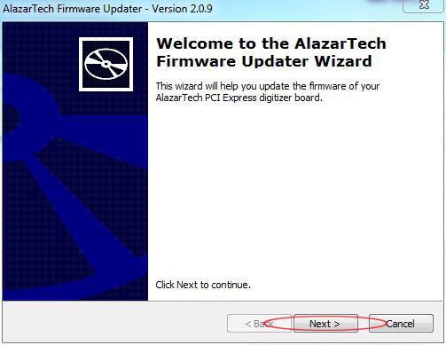
- Click NEXT

- For Select a firmware file choose the correspondent firmware (.pof file) you have previously downloaded
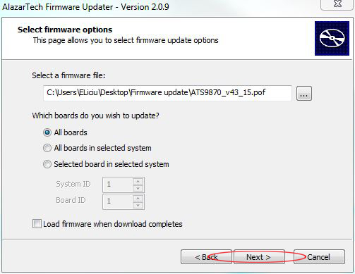
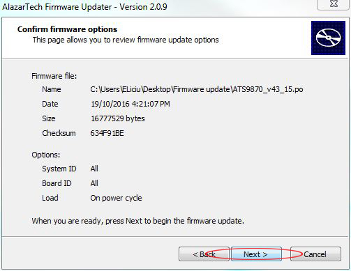
- Click NEXT
- Allow your computer to be shut down (not just a restart, as FPGA is loaded on power-on)
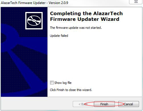
- Turn on your computer
- Run AlazarDSO software
- Press F4 key. It will display the Board Properties page. One of the lines is FPGA version. Make sure the version number displayed corresponds to the version of the FPGA you downloaded (.exe file name).
[1011] How can I use ApiFlags utility to log API calls I make to the AlazarTech DLL for Windows?
Lien vers cette réponse: Copié
AlazarTech prides itself in the quality of technical support it provides to its customers. Whenever a customer reports a problem, our technical staff try to reproduce the probem in our lab.
There are many occasions, however, in which it is impossible for our engineers to reproduce the problem. For example, the customer's software may include calls to other equipment (motor controllers, lasers etc.) and in the absence of this equipment, we cannot run customer's software. Or, the customer may not want to disclose the source code of their software for intellectual property protection purposes.
AlazarTech has developed a unique software utility for Windows called APIFlags, using which the customer can report problems to our software engineers without disclosing any source code.
Linux programmers can do API logging as well, but they must modify their .alazarrc file to enable or disable logging. For more details, see How can I log API calls I make to the AlazarTech library in Linux?
ApiFlags utility sets a flag in the AlazarTech Windows DLL that forces each API call made to the DLL to be logged to a text file. In vast majority of cases, the information contained in this log files gives our software engineers sufficient information to identify the problem in the customer's software and suggest a solution.
Latest versions of AlazarDSO software also provide this API logging capability. Go to Tools menu, select Debugging and click on Start logging calls made to ATSAPI.dll.
Cautionary note: After you are done debugging, you MUST disable API logging function using APIFlags or AlazarDSO. If you do not, your software's performance may be severely degraded, as writing to file is a slow function.
Here is how you would use APIFlags:
- Download the ApiFlags setup program from our website.
- ApiFlags is packaged as a zip file that contains the executable and a short menual on how to use it
- Extract ApiFlagsSetup.exe from the zip file and run it to install ApiFlags.exe on your computer
- Exit all applications that use AlazarTech DLL
- Run ApiFlags.exe
- Check the ApiFlags "Log API calls" button, and press the "Apply" button to enable logging
- Run your application until you see the problem, then exit your application
- Click on the ApiFlags "View" button to open the log file in notepad, and save this file to your "Documents" folder. You can email us this log file later
- Click on the ApiFlags "Delete" button to delete the log file from your temporary files directory
- Uncheck the ApiFlags "Log API calls" button and press the "Apply" button to disable logging
- If you do not dsable logging, your program's performance may be severely degraded
- Exit ApiFlags.exe
[1010] Skipping DMA buffers in LabVIEW
Lien vers cette réponse: Copié
In LabVIEW, special care must be given to managing DMA buffers.
First, LabVIEW will only use buffers allocated by LabVIEW itself.
Second, the buffers allocated by LabVIEW do not satisfy the alignment requirement of Alazar driver’s library.
The combination of the above two restrictions, imposes the restriction of the DMA buffers be allocated independent of LabVIEW. These memory aligned buffers are used by the DMA engine to transfer the data from the digitizer board memory into PC memory, and once the transfer is finished, one needs to copy the content into a LabVIEW buffer. Only then the data can be processed by LabVIEW VI’s.
In some situations you may find it more convenient to allow the driver library to allocate and manage a list of buffers available to be filled by the board. In these applications you should call AlazarBeforeAsyncRead() with the AMDA_ALLOC_BUFFERS option selected in the “Flags” parameter.
This option will cause the library to allocate and manage a list of buffers available to be filled by the board. The application must call AlazarWaitNextAsyncBufferComplete to wait for a buffer to be filled. When the board receives sufficient trigger events to fill a buffer, the API will copy the data from the internal buffer to the user-supplied/LabVIEW buffer.
The process of copying DMA buffer into a new location introduces some delay and slows down the overall chain of data acquisition. If the speed at which buffers are transferred from DMA buffers into LabVIEW buffers becomes slower that the speed at which the board is acquiring data, a buffer overflow will happen.
In some situations, it may be acceptable for the application to prevent buffer overflow at the expense of losing some of the DMA buffers. In other words, if we are able to monitor the number of DMA buffers pending for transfer to LabVIEW buffers, then we might decide to momentarily skip DMA buffers (and loose the content) to reduce the pending buffer queue.
AlazarGetParameter() is the function that allows to query the DMA queue status, using one of the following parameters:
GET_ASYNC_BUFFERS_PENDING 0x10000050 | Get the number of DMA buffers that have been queued by an application to this board. |
GET_ASYNC_BUFFERS_PENDING_FULL 0x10000051 | Get the number of DMA buffers for this board that are full and waiting to be processed by the application. |
GET_ASYNC_BUFFERS_PENDING_EMPTY 0x10000052 | Get the number of DMA buffers for this board that are empty and waiting to be filled by the board. |
If the application decides to skip a buffer, then in the call to AlazarWaitNextAsyncBufferComplete() it will pass BytesToCopy = 0. This way the content of the DMA buffer is not copied and the DMA buffer is simply returned to the queue of buffers to be used for DMA transfer.
[1009] I installed an ATS9440 in a new PC running Windows 7 Professional. After installing the driver, the board is not detected in Device Manager. I tried 3 different PCIe slots available on the motherboard, no success. The graphics card works in all 3 slots. Motherboard model: EVGA 131-HE-E095-KR CPU: Intel i7
Lien vers cette réponse: Copié
The motherboard EVGA 131-HE-E095-KR supports PCIe Gen3. After a great deal of testing, it was discovered that this particular motherboard's BIOS had a bug in that it did not negotiate a PCIe link properly if the "PCIe Slot Generation" is set to "Auto" and the Add-on board is not a Gen3 board. A BIOS update (when available) would fix this bug. In the meantime, we helped the customer find a workaround.
ATS9440 is a PCIe Gen1 board. According to PCIe specification, a motherboard slot that supports Gen3 must also be able to negotiate a Gen2 or Gen1 link with Gen2 or Gen1 add-on boards. EVGA 131-HE-E095-KR does not seem to be meeting this specification with the current BIOS.
Once the customer changed the "PCI Slot Generation" field to GEN1, the motherboard was able to successfully detect ATS9440. The problem was that this BIOS did not do a good job of negotiating the link speed in "Auto" mode.
Workaround was to set the "PCIe Slot Generation" field to "GEN1".
In case a similar problem happens with your computer, follow the following steps:
- Always make sure your BIOS is the latest version. Check manufacturer's web site.
- In the BIOS, look for a field that allows you to set the "PCIe Generation" for the slots and set it to match the PCIe Generation of the AlazarTech board you are trying to install.
- Contact the manufacturer of the motherboard to report the bug in their BIOS.
[1008] I installed an ATS860 board in a PCI slot of a Windows XP machine. Then I installed the driver which I downloaded from Alazar website. I went to the Device Manager to check if the board is properly detected. But I can only see a PCI device with a yellow question mark in front of it.
Lien vers cette réponse: Copié
Possible cause 1: BAR2 range is too small.
Possible solution 1: To make sure your board is functional, try installing the board on another computer. Once you have a computer where the board is recognized, run AlazarPatchEEPROM utility that you can download from Alazar website. Move the board back to the original computer and check if it works.
[1007] I have used waveform digitizers from other manufacturers. A big problem with their board was that if we run our software and there is no board in the system, the computer would crash with a "blue-screen". We'd like to avoid this "Crashing-Driver Syndrome". Can we trust that your drivers will not do the same?
Lien vers cette réponse: Copié
You can rest assured that AlazarTech drivers will not "blue-screen" crash if the board is not present. We return an error code that the calling program can use to find out if the board was present in the system or not. This avoids the "Crashing-Driver Syndrome" that some other manufacturers have - even though their products are usually twice as expensive as AlazarTech.
[1006] I am programming your card in C/C++. I want to disable trigger timeout. How do I do it? There does not seem to be a flag I can set or reset to disable it.
Lien vers cette réponse: Copié
You can disable trigger timeout by setting a timeout value of zero. You can do this by calling AlazarSetTriggerTimeout (0)
[1005] We injected a 10 KHz, 1Vp-p sine wave into the ATS850 using AlazarDSO software. We selected 50Ω impedance and AC coupling. Software displayed a sine wave of only 300 mV amplitude. This does not seem right.Is my hardware defective?
Lien vers cette réponse: Copié
Your hardware is functioning exactly as it should. Note that the lower cut-off frequency in AC coupled mode when you have 50Ω impedance is 100 KHz. This means that any signal lower than approximately 150 KHz will be attenuated (even 100 KHz signals will be attenuated by about 30%) Since your signal is only 10 KHz, it will be attenuated much more.
To measure your signal using AC coupling, set input impedance to be 1 MΩ The lower cut-off frequency in AC coupled mode when you have 1 MΩ impedance is 10 Hz.
[1004] I installed my ATS850 in my PC. I see that there are four LEDs that are always lit, whereas the others go on and off as I operate the device. Is this normal?
Lien vers cette réponse: Copié
Yes, this is perfectly normal. The four LEDs that are always on signify that four of the most important parts of the circuit are working properly. The three other LEDs show the status of BUSY, TRIGGERED, and PCI ACCESS flags. They tend to go on and off depending on how you exercise the card through software.
[1003] How long is your calibration valid for?
Lien vers cette réponse: Copié
Just like any other instrument, we recommend that you have the calibration verified at least once a year. Recalibration due date is always shown on the calibration label affixed to the digitizer card.
[1002] How can I program your ATS digitizers?
Lien vers cette réponse: Copié
If you want to write software using C/C++/C#, MATLAB, Python or LabVIEW, you will have to purchase the ATS-SDK (software development kit) in order to be able to program our digitizers. ATS-SDK comes with a reference manual, header files as well as sample programs that show you how to use our API.
[1001] What operating systems do you support?
Lien vers cette réponse: Copié
AlazarTech products support Windows® and Linux® operating systems.
For Windows, AlazarTech Windows driver installation programs will detect the operating system and install the appropriate driver files. Windows support includes Windows 11, Windows 10, Windows Server® 2019, and Windows Server 2016. As Windows Server 2019 and 2016 are seldom used by our customers, they are expected to work but are not regularly tested with each software release. If there are issues related to Windows Server 2016 or 2019, tech support may not be as rapid as for other operating systems.
Only 64-bit Windows operating systems are supported. The last 32-bit Windows driver is version 5.10.24, which supports Windows 7.
Microsoft mainstream support ended in 2018 for Windows 8.1 and Windows Server 2012 R2. As such, AlazarTech has ceased development on these operating systems. Current software and driver releases may work with these operating systems but they are not officially supported.
Due to lack of demand and due to the fact that Microsoft no longer supports these operating systems, AlazarTech no longer supports Windows 8, Windows 7, Windows XP, Windows Vista, Windows Server 2012, Windows Server 2008 R2, and Windows Server 2008.
AlazarTech offers Dynamic Kernel Module Support (DKMS) drivers for AlazarTech waveform digitizers for the following Linux distributions: Ubuntu, Debian, and RHEL®.
AlazarTech DKMS drivers may work for other Linux distributions but they have not been tested and technical support may be limited. Only 64-bit Linux operating systems are supported.
[1000] What bus do your current products support?
Lien vers cette réponse: Copié
AlazarTech products currently support PCI and PCI Express bus.